MCP23018/MCP23S18
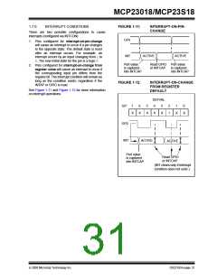
2.2
AC CHARACTERISTICS
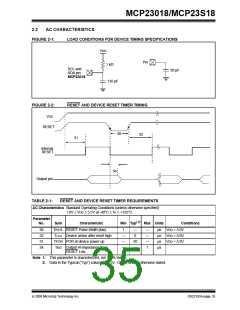
FIGURE 2-1:
LOAD CONDITIONS FOR DEVICE TIMING SPECIFICATIONS
VDD
Pin
1 kΩ
SCL and
SDA pin
50 pF
MCP23018
135 pF
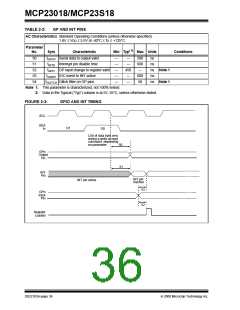
FIGURE 2-2:
RESET AND DEVICE RESET TIMER TIMING
VDD
RESET
30
32
31
Internal
RESET
34
Output pin
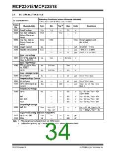
TABLE 2-1:
RESET AND DEVICE RESET TIMER REQUIREMENTS
AC Characteristics Standard Operating Conditions (unless otherwise specified)
1.8V ≤ VDD ≤ 5.5V at -40°C ≤ TA ≤ +125°C.
Parameter
No.
Sym
Characteristic
Min Typ( 2) Max Units
Conditions
30
32
31
34
TRSTL RESET Pulse Width (low)
THLD Device active after reset high
TPOR POR at device power up
1
—
0
—
—
—
1
µs VDD = 5.0V
µs VDD = 5.0V
µs VDD = 5.0V
µs
—
—
—
20
—
TioZ Output Hi-impedance from
RESET Low
Note 1: This parameter is characterized, not 100% tested.
2: Data in the Typical (“Typ”) column is at 5V, +25°C, unless otherwise stated.
© 2008 Microchip Technology Inc.
DS22103A-page 35

 MICROCHIP [ MICROCHIP ]