MCP23018/MCP23S18
1.7.6
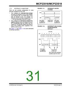
INTERRUPT CONDITIONS
FIGURE 1-11:
INTERRUPT-ON-PIN-
CHANGE
There are two possible configurations to cause
interrupts (configured via INTCON):
GPx
1. Pins configured for interrupt-on-pin-change
will cause an interrupt to occur if a pin changes
to the opposite state. The default state is reset
after an interrupt occurs. For example, an
interrupt occurs by an input changing from 1to
0. The new initial state for the pin is a logic 0.
INT
ACTIVE
ACTIVE
Port value
is captured
into INTCAP
Read GPIO Port value
2. Pins configured for interrupt-on-change from
register value will cause an interrupt to occur if
the corresponding input pin differs from the
register bit. The interrupt condition will remain as
long as the condition exists, regardless if the
INTAP or GPIO is read.
or INTCAP
is captured
into INTCAP
FIGURE 1-12:
INTERRUPT-ON-CHANGE
FROM REGISTER
DEFAULT
See Figure 1-11 and Figure 1-12 for more information
on interrupt operations.
DEFVAL
GP:
7
6
5
4
3
2
1
1
0
X
X
X
X
X
X
X
GP2
INT
ACTIVE
ACTIVE
Port value
is captured
into INTCAP
Read GPIO
or INTCAP
(INT clears only if interrupt
condition does not exist.)
© 2008 Microchip Technology Inc.
DS22103A-page 31

 MICROCHIP [ MICROCHIP ]