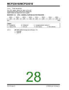
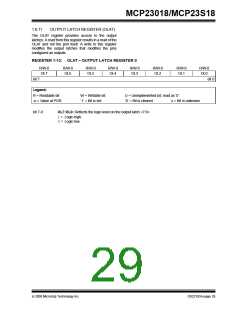
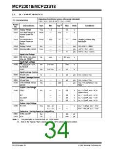
MCP23018/MCP23S18
1.7.2
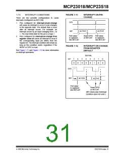
IOC FROM PIN CHANGE
1.7
Interrupt Logic
If enabled, the MCP23X18 will generate an interrupt if
a mismatch condition exists between the current port
value and the previous port value. Only IOC enabled
pins will be compared. See GPINTEN and INTCON
registers.
If enabled, the MCP23X18 activates the INTn interrupt
output when one of the port pins changes state or when
a pin does not match the pre-configured default. Each
pin is individually configurable as follows:
• Enable/disable interrupt via GPINTEN
• Can interrupt on either pin change or change from
default as configured in DEFVAL
1.7.3
IOC FROM REGISTER DEFAULT
If enabled, the MCP23X18 will generate an interrupt if
a mismatch occurs between the DEFVAL register and
the port. Only IOC enabled pins will be compared. See
GPINTEN, INTCON, and DEFVAL registers.
Both conditions are referred to as Interrupt on Change
(IOC).
The Interrupt Control (INT) Module uses the following
registers/bits:
1.7.4
INTERRUPT OPERATION
• IOCON.MIRROR - controls if the two interrupt
pins mirror each other.
The INTn interrupt output can be configured as “active
low”, “active high”, or “open drain” via the IOCON
register.
• GPINTEN - Interrupt enable register
• INTCON - Controls the source for the IOC
Only those pins that are configured as an input (IODIR
register) with interrupt-on-change (IOC) enabled
(GPINTEN register) can cause an interrupt. Pins
defined as an output have no effect on the interrupt
output pin.
• DEFVAL - Contains the register default for IOC
operation
1.7.1
INTA AND INTB
There are two interrupt pins, INTA and INTB. By
default, INTA is associated with GPAn pins (Port A) and
INTB is associated with GPBn pins (Port B). Each port
has an independent signal which is cleared if its
associated GPIO or INTCAP register is read.
Input change activity on a port input pin that is enabled
for IOC will generate an internal device interrupt and
the device will capture the value of the port and copy it
into INTCAP.
The first interrupt event will cause the port contents to
be copied into the INTCAP register. Subsequent
interrupt conditions on the port will not cause an
interrupt to occur as long as the interrupt is not cleared
by a read of INTCAP or GPIO.
1.7.1.1
Mirroring the INT pins
Additionally, the INTn pins can be configured to mirror
each other so that any interrupt will cause both pins to
go active. This is controlled via IOCON.MIRROR.
If IOCON.MIRROR = 0, the internal signals are routed
independently to the INTA and INTB pads.
1.7.5
CLEARING INTERRUPTS
The interrupt will remain active until the INTCAP or
GPIO register is read (depending on IOCON.INTCC).
Writing to these registers will not affect the interrupt.
The interrupt condition will be cleared after the LSb of
the data is clocked out during a Read command of
GPIO or INTCAP (depending on IOCON.INTCC).
If IOCON.MIRROR = 1, the internal signals are OR’ed
together and routed to the INTn pads. In this case, the
interrupt will only be cleared if the associated GPIO or
INTCAP is read (see Table 1-6).
TABLE 1-6:
INTERRUPT OPERATION
(IOCON.MIRROR = 1)
Note:
Assuming IOCON.INTCC = 0 (INT cleared
on GPIO read): The value in INTCAP can
be lost if GPIO is read before INTCAP
while another IOC is pending. After read-
ing GPIO, the interrupt will clear and then
set due to the pending IOC, causing the
INTCAP register to update.
Interrupt
Condition
Interupt
Read Port N*
Result
GPIOA
GPIOB
Port A
Port B
Port A
Port B
Port A
Port B
Clear
Unchanged
Unchanged
Clear
GPIOA and
GPIOB
Unchanged
Unchanged
Clear
Both Port A
and Port B
* Port n = GPIOn or INTCAPn
DS22103A-page 30
© 2008 Microchip Technology Inc.

 MICROCHIP [ MICROCHIP ]