HCS301
3.2
SYNC (Synchronization Counter)
3.6
CONFIG (Configuration Word)
This is the 16-bit synchronization value that is used to
create the hopping code for transmission. This value
will increment after every transmission.
The Configuration Word is a 16-bit word stored in
EEPROM array that is used by the device to store
information used during the encryption process, as well
as the status of option configurations. The following
sections further explain these bits.
3.3
Reserved
Must be initialized to 0000H.
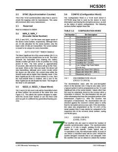
TABLE 3-2:
Bit Number
CONFIGURATION WORD
Bit Description
3.4
SER_0, SER_1
(Encoder Serial Number)
0
1
2
3
4
5
6
7
8
Discrimination Bit 0
Discrimination Bit 1
Discrimination Bit 2
Discrimination Bit 3
Discrimination Bit 4
Discrimination Bit 5
Discrimination Bit 6
Discrimination Bit 7
Discrimination Bit 8
Discrimination Bit 9
Overflow Bit 0 (OVR0)
Overflow Bit 1 (OVR1)
Low Voltage Trip Point Select
(VLOW SEL)
SER_0 and SER_1 are the lower and upper words of
the device serial number, respectively. Although there
are 32 bits allocated for the serial number, only the
lower order 28 bits are transmitted. The serial number
is meant to be unique for every transmitter.
3.4.1
AUTO-SHUTOFF TIMER ENABLE
The Most Significant bit of the serial number (Bit 31) is
used to turn the Auto-shutoff timer on or off. This timer
prevents the transmitter from draining the battery
should a button get stuck in the on position for a long
period of time. The time period is approximately
25 seconds, after which the device will go to the Time-
out mode. When in the Time-out mode, the device will
stop transmitting, although since some circuits within
the device are still active, the current draw within the
Shutoff mode will be higher than Standby mode. If the
Most Significant bit in the serial number is a one, then
the Auto-shutoff timer is enabled, and a zero in the
Most Significant bit will disable the timer. The length of
the timer is not selectable.
9
10
11
12
13
14
15
Baud rate Select Bit 0 (BSL0)
Baud rate Select Bit 1 (BSL1)
Reserved, set to 0
3.6.1
DISCRIMINATION VALUE
(DISC0 TO DISC9)
The discrimination value aids the post-decryption
check on the decoder end. It may be any value, but in
a typical system it will be programmed as the 10 Least
Significant bits of the serial number. Values other than
this must be separately stored by the receiver when a
transmitter is learned. The discrimination bits are part
of the information that form the encrypted portion of the
transmission (Figure 4-2). After the receiver has
decrypted a transmission, the discrimination bits are
checked against the receiver’s stored value to verify
that the decryption process was valid. If the discrimina-
tion value was programmed as the 10 LSb’s of the
serial number then it may merely be compared to the
respective bits of the received serial number; saving
EEPROM space.
3.5
SEED_0, SEED_1 (Seed Word)
The 2-word (32-bit) seed code will be transmitted when
all three buttons are pressed at the same time (see
Figure 4-2). This allows the system designer to imple-
ment the secure learn feature or use this fixed code
word as part of a different key generation/tracking pro-
cess.
3.6.2
OVERFLOW BITS
(OVR0, OVR1)
The overflow bits are used to extend the number of
possible synchronization values. The synchronization
counter is 16 bits in length, yielding 65,536 values
before the cycle repeats. Under typical use of
10 operations a day, this will provide nearly 18 years of
use before a repeated value will be used. Should the
system designer conclude that is not adequate, then
the overflow bits can be utilized to extend the number
2001 Microchip Technology Inc.
DS21143B-page 7

 MICROCHIP [ MICROCHIP ]