HCS301
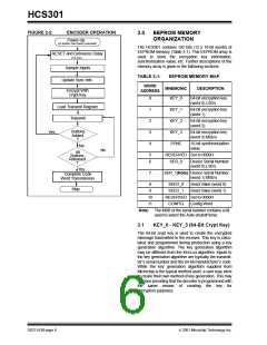
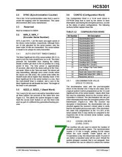
FIGURE 2-2:
ENCODER OPERATION
3.0
EEPROM MEMORY
ORGANIZATION
Power-Up
(A button has been pressed)
The HCS301 contains 192 bits (12 x 16-bit words) of
EEPROM memory (Table 3-1). This EEPROM array is
used to store the encryption key information,
synchronization value, etc. Further descriptions of the
memory array is given in the following sections.
RESET and Debounce Delay
(10 ms)
Sample Inputs
TABLE 3-1:
EEPROM MEMORY MAP
Update Sync Info
WORD
ADDRESS
MNEMONIC
DESCRIPTION
Encrypt With
Crypt Key
0
1
2
3
4
KEY_0
64-bit encryption key
(word 0) LSb’s
Load Transmit Register
Transmit
KEY_1
KEY_2
KEY_3
SYNC
64-bit encryption key
(word 1)
64-bit encryption key
(word 2)
Buttons
Added
?
Yes
64-bit encryption key
(word 3) MSb’s
16-bit synchronization
value
No
No
All
Buttons
Released
?
5
6
RESERVED Set to 0000H
SER_0 Device Serial Number
(word 0) LSb’s
Yes
7
SER_1(Note) Device Serial Number
Complete Code
Word Transmission
(word 1) MSb’s
8
9
SEED_0
SEED_1
Seed Value (word 0)
Seed Value (word 1)
Stop
10
11
RESERVED Set to 0000H
CONFIG Config Word
Note: The MSB of the serial number contains a bit
used to select the Auto-shutoff timer.
3.1
KEY_0 - KEY_3 (64-Bit Crypt Key)
The 64-bit crypt key is used to create the encrypted
message transmitted to the receiver. This key is calcu-
lated and programmed during production using a key
generation algorithm. The key generation algorithm
may be different from the KEELOQ algorithm. Inputs to
the key generation algorithm are typically the transmit-
ter’s serial number and the 64-bit manufacturer’s code.
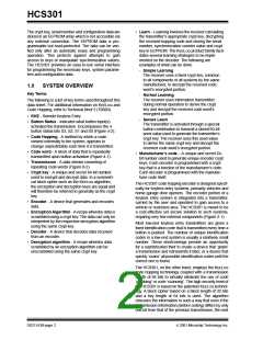
While the key generation algorithm supplied from
Microchip is the typical method used, a user may elect
to create their own method of key generation. This may
be done providing that the decoder is programmed with
the same means of creating the key for
decryption purposes.
DS21143B-page 6
2001 Microchip Technology Inc.

 MICROCHIP [ MICROCHIP ]