HCS301
coded transmission will be completely different. Statis-
tically, if only one bit in the 32-bit string of information
changes, greater than 50 percent of the coded trans-
mission bits will change.
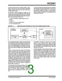
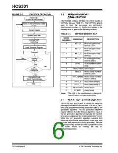
The crypt key generation typically inputs the transmitter
serial number and 64-bit manufacturer’s code into the
key generation algorithm (Figure 1-1). The manufac-
turer’s code is chosen by the system manufacturer and
must be carefully controlled as it is a pivotal part of the
overall system security.
As indicated in the block diagram on page one, the
HCS301 has a small EEPROM array which must be
loaded with several parameters before use; most often
programmed by the manufacturer at the time of produc-
tion. The most important of these are:
• A 28-bit serial number, typically unique for every
encoder
• A crypt key
• An initial 16-bit synchronization value
• A 16-bit configuration value
FIGURE 1-1:
CREATION AND STORAGE OF CRYPT KEY DURING PRODUCTION
Production
Programmer
HCS301
Transmitter
Serial Number
EEPROM Array
Serial Number
Crypt Key
Sync Counter
.
Key
Crypt
Key
.
.
Manufacturer’s
Code
Generation
Algorithm
The 16-bit synchronization counter is the basis behind
the transmitted code word changing for each transmis-
sion; it increments each time a button is pressed. Due
to the code hopping algorithm’s complexity, each incre-
ment of the synchronization value results in greater
than 50% of the bits changing in the transmitted code
word.
A transmitter must first be ‘learned’ by the receiver
before its use is allowed in the system. Learning
includes calculating the transmitter’s appropriate crypt
key, decrypting the received hopping code and storing
the serial number, synchronization counter value and
crypt key in EEPROM.
In normal operation, each received message of valid
format is evaluated. The serial number is used to deter-
mine if it is from a learned transmitter. If from a learned
transmitter, the message is decrypted and the synchro-
nization counter is verified. Finally, the button status is
checked to see what operation is requested. Figure 1-3
shows the relationship between some of the values
stored by the receiver and the values received from
the transmitter.
Figure 1-2 shows how the key values in EEPROM are
used in the encoder. Once the encoder detects a button
press, it reads the button inputs and updates the syn-
chronization counter. The synchronization counter and
crypt key are input to the encryption algorithm and the
output is 32 bits of encrypted information. This data will
change with every button press, its value appearing
externally to ‘randomly hop around’, hence it is referred
to as the hopping portion of the code word. The 32-bit
hopping code is combined with the button information
and serial number to form the code word transmitted to
the receiver. The code word format is explained in
greater detail in Section 4.0.
A receiver may use any type of controller as a decoder,
but it is typically a microcontroller with compatible firm-
ware that allows the decoder to operate in conjunction
with an HCS301 based transmitter. Section 7.0
provides detail on integrating the HCS301 into a sys-
tem.
2001 Microchip Technology Inc.
DS21143B-page 3

 MICROCHIP [ MICROCHIP ]