HCS301
TABLE 2-1:
PIN DESCRIPTIONS
2.0
DEVICE OPERATION
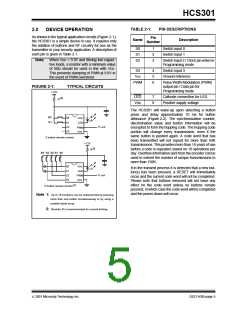
As shown in the typical application circuits (Figure 2-1),
the HCS301 is a simple device to use. It requires only
the addition of buttons and RF circuitry for use as the
transmitter in your security application. A description of
each pin is given in Table 2-1.
Pin
Number
Name
Description
Switch input 0
S0
S1
S2
1
2
3
Switch input 1
Note: When VDD > 9.0V and driving low capaci-
tive loads, a resistor with a minimum value
of 50Ω should be used in line with VDD.
This prevents clamping of PWM at 9.0V in
the event of PWM overshoot.
Switch input 2 / Clock pin when in
Programming mode
S3
VSS
4
5
6
Switch input 3
Ground reference
PWM
Pulse Width Modulation (PWM)
output pin / Data pin for
Programming mode
FIGURE 2-1:
TYPICAL CIRCUITS
+12V
LED
VDD
7
8
Cathode connection for LED
Positive supply voltage
R (2)
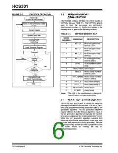
The HCS301 will wake-up upon detecting a button
press and delay approximately 10 ms for button
debounce (Figure 2-2). The synchronization counter,
discrimination value and button information will be
encrypted to form the hopping code. The hopping code
portion will change every transmission, even if the
same button is pushed again. A code word that has
been transmitted will not repeat for more than 64K
transmissions. This provides more than 18 years of use
before a code is repeated; based on 10 operations per
day. Overflow information sent from the encoder can be
used to extend the number of unique transmissions to
more than 192K.
B0
B1
S0
VDD
LED
S1
S2
S3
Tx out
PWM
VSS
2 button remote control
+12V
R(2)
B4 B3 B2 B1 B0
S0
VDD
LED
PWM
VSS
If in the transmit process it is detected that a new but-
ton(s) has been pressed, a RESET will immediately
occur and the current code word will not be completed.
Please note that buttons removed will not have any
effect on the code word unless no buttons remain
pressed; in which case the code word will be completed
and the power-down will occur.
S1
S2
S3
Tx out
5 button remote control (1)
Note 1: Up to 15 functions can be implemented by pressing
more than one button simultaneously or by using a
suitable diode array.
2: Resistor R is recommended for current limiting.
2001 Microchip Technology Inc.
DS21143B-page 5

 MICROCHIP [ MICROCHIP ]