25AA512/25LC512
TABLE 1-2:
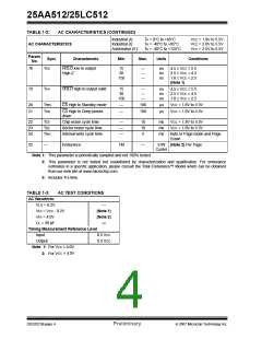
AC CHARACTERISTICS (CONTINUED)
Industrial (I):
Industrial (I):
Automotive (E):
TA = 0°C to +85°C
TA = -40°C to +85°C
TA = -40°C to +125°C
VCC = 1.8V to 5.5V
VCC = 2.0V to 5.5V
VCC = 2.5V to 5.5V
AC CHARACTERISTICS
Param.
Sym.
No.
Characteristic
Min.
Max.
Units
Conditions
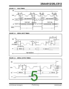
18
THZ
HOLD low to output
High-Z
15
30
150
—
—
—
ns
ns
ns
4.5 ≤ VCC ≤ 5.5
2.5 ≤ VCC < 4.5
1.8 ≤ VCC < 2.5
(Note 1)
19
THV
HOLD high to output valid
15
30
150
—
—
—
ns
ns
ns
4.5 ≤ VCC ≤ 5.5
2.5 ≤ VCC < 4.5
1.8 ≤ VCC < 2.5
20
21
TREL
TPD
CS High to Standby mode
—
—
100
100
μs
μs
VCC = 1.8V to 5.5V
VCC = 1.8V to 5.5V
CS High to Deep power-
down
22
23
24
TCE
TSE
TWC
Chip erase cycle time
Sector erase cycle time
Internal write cycle time
—
—
—
10
10
5
ms
ms
ms
VCC = 1.8V to 5.5V
VCC = 1.8V to 5.5V
Byte or Page mode and Page
Erase
25
—
Endurance
1M
—
E/W (Note 2) Per Page
Cycles
Note 1: This parameter is periodically sampled and not 100% tested.
2: This parameter is not tested but established by characterization and qualification. For endurance
estimates in a specific application, please consult the Total Endurance™ Model which can be obtained
from our web site at www.microchip.com.
3: Includes THI time.
TABLE 1-3:
AC TEST CONDITIONS
AC Waveform:
VLO = 0.2V
—
VHI = VCC - 0.2V
(Note 1)
(Note 2)
—
VHI = 4.0V
CL = 30 pF
Timing Measurement Reference Level
Input
0.5 VCC
0.5 VCC
Output
Note 1: For VCC ≤ 4.0V
2: For VCC > 4.0V
DS22021B-page 4
Preliminary
© 2007 Microchip Technology Inc.

 MICROCHIP [ MICROCHIP ]