PIC12CE67X
The PSA and PS2:PS0 bits (OPTION<3:0>) determine
the prescaler assignment and prescale ratio.
7.3
Prescaler
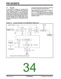
An 8-bit counter is available as a prescaler for the
Timer0 module, or as a postscaler for the Watchdog
Timer, respectively (Figure 7-6). For simplicity, this
counter is being referred to as “prescaler” throughout
this data sheet. Note that there is only one prescaler
available which is mutually exclusively shared between
the Timer0 module and the Watchdog Timer. Thus, a
prescaler assignment for the Timer0 module means
that there is no prescaler for the Watchdog Timer, and
vice-versa.
When assigned to the Timer0 module, all instructions
writing to the TMR0 register (e.g. CLRF 1, MOVWF 1,
BSF 1,x....etc.) will clear the prescaler.When assigned
to WDT, a CLRWDT instruction will clear the prescaler
along with the Watchdog Timer. The prescaler is not
readable or writable.
FIGURE 7-6: BLOCK DIAGRAM OF THE TIMER0/WDT PRESCALER
Data Bus
8
CLKOUT (=Fosc/4)
M
U
X
1
0
0
1
M
U
X
GP2/T0CKI/
AN2/INT
SYNC
2
Cycles
TMR0 reg
T0SE
T0CS
Set flag bit T0IF
on Overflow
PSA
0
1
8-bit Prescaler
M
U
X
Watchdog
Timer
8
8 - to - 1MUX
PS2:PS0
PSA
1
0
WDT Enable bit
M U X
PSA
WDT
Time-out
Note: T0CS, T0SE, PSA, PS2:PS0 are (OPTION<5:0>).
DS40181B-page 34
Preliminary
1998 Microchip Technology Inc.

 MICROCHIP [ MICROCHIP ]