PIC12CE67X
7.3.1
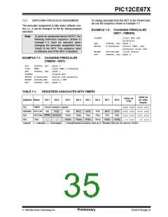
SWITCHING PRESCALER ASSIGNMENT
To change prescaler from the WDT to the Timer0 mod-
ule use the sequence shown in Example 7-2.
The prescaler assignment is fully under software con-
trol, i.e., it can be changed “on the fly” during program
execution.
EXAMPLE 7-2: CHANGING PRESCALER
(WDT→TIMER0)
Note: To avoid an unintended device RESET, the
following instruction sequence (shown in
Example 7-1) must be executed when
changing the prescaler assignment from
Timer0 to the WDT. This sequence must
be followed even if the WDT is disabled.
CLRWDT
;Clear WDT and
;prescaler
STATUS, RP0 ;Bank 1
b'xxxx0xxx' ;Select TMR0, new
;prescale value and
OPTION_REG ;clock source
STATUS, RP0 ;Bank 0
BSF
MOVLW
MOVWF
BCF
EXAMPLE 7-1: CHANGING PRESCALER
(TIMER0→WDT)
BCF
STATUS, RP0 ;Bank 0
CLRF
BSF
TMR0
;Clear TMR0 & Prescaler
STATUS, RP0 ;Bank 1
CLRWDT
;Clears WDT
MOVLW b'xxxx1xxx' ;Select new prescale
MOVWF OPTION_REG ;value & WDT
STATUS, RP0 ;Bank 0
BCF
TABLE 7-1:
REGISTERS ASSOCIATED WITH TIMER0
Value on
Value on
POR
Address Name
Bit 7
Bit 6
Bit 5
Bit 4
Bit 3
Bit 2
Bit 1
Bit 0
all other
Resets
01h
TMR0
Timer0 module’s register
xxxx xxxx uuuu uuuu
0000 000x 0000 000u
1111 1111 1111 1111
0Bh/8Bh INTCON
GIE
OPTION GPPU INTEDG
TRIS
PEIE
T0IE
T0CS
TRIS5
INTE
T0SE
TRIS4
GPIE
PSA
T0IF
PS2
INTF
PS1
GPIF
PS0
81h
85h
—
—
TRIS3
TRIS2
TRIS1
TRIS0 --11 1111 --11 1111
Legend: x= unknown, u= unchanged, -= unimplemented locations read as '0'. Shaded cells are not used by Timer0.
1998 Microchip Technology Inc.
Preliminary
DS40181B-page 35

 MICROCHIP [ MICROCHIP ]