KSZ8795CLX
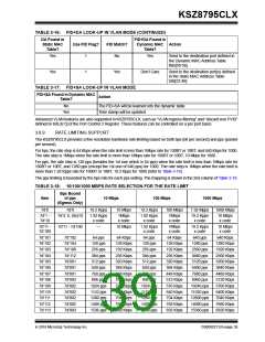
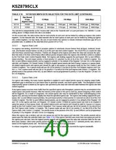
TABLE 3-18: 10/100/1000 MBPS RATE SELECTION FOR THE RATE LIMIT (CONTINUED)
Bps Bound
Item
of pps
10 Mbps
100 Mbps
1000 Mbps
(Egress Only)
7d’114
7d’115
7d’003
7d’003
1664 pps
1792 pps
896 Kbps
969 Kbps
1664 pps
1792 pps
896 Kbps
969 Kbps
16640 pps
17920 pps
8960 Kbps
9690 Kbps
The rate limit is independently on the “receive side” and on the “transmit side” on a per port basis. For 10BASE-T, a rate
setting above 10 Mbps means the rate is not limited.
On the receive side, the data receive rate for each priority at each port can be limited by setting up ingress rate control
registers. On the transmit side, the data transmit rate for each queue at each port can be limited by setting up egress
rate control registers. For bps mode, the size of each frame has options to include minimum interframe gap (IFG) or
preamble byte, in addition to the data field (from packet DA to FCS).
3.6.9.1
Ingress Rate Limit
For ingress rate limiting, KSZ8795CLX provides options to selectively choose frames from all types; multicast, broad-
cast, and flooded unicast frames via bits [3:2] of the port rate limit control register. The KSZ8795CLX counts the data
rate from those selected type of frames. Packets are dropped at the ingress port when the data rate exceeds the spec-
ified rate limit or the flow control takes effect without packet dropped when the ingress rate limit flow control is enabled
by the Port Rate Limit Control Register Bit[4]. The ingress rate limiting supports the port-based, 802.1p and DiffServ-
based priorities. The port-based priority is fixed priority 0-3 selection by bits [4:3] of the Port Control 0 register. The
802.1p and DiffServ-based priority can be mapped to priority 0-3 by default of the Register 128 and 129. In the ingress
rate limit, set Register 135 Global Control 19 Bit[3] to enable queue-based rate limit if using 2-queue or 4-queue mode.
All related ingress ports and egress port should be split to two-queue or four-queue mode by the Port Control 9 and
Control 0 registers. The 4-queue mode will use Q0-Q3 for priority 0-3 by bits [6:0] of the Port Register Ingress Limit Con-
trol 1-4. The 2-queue mode will use Q0-Q1 for priority 0-1 by bits [6:0] of the port ingress limit control 1-2 registers. The
priority levels in the packets of the 802.1p and DiffServ can be programmed to priority 0-3 via the Register 128 and 129
for a re-mapping.
3.6.9.2
Egress Rate Limit
For egress rate limiting, the leaky bucket algorithm is applied to each output priority queue for shaping output traffic.
Interframe gap is stretched on a per frame base to generate smooth, non-burst egress traffic. The throughput of each
output priority queue is limited by the egress rate specified by the data rate selection table followed the egress rate limit
control registers.
If any egress queue receives more traffic than the specified egress rate throughput, packets may be accumulated in the
output queue and packet memory. After the memory of the queue or the port is used up, packet dropping or flow control
will be triggered. As a result of congestion, the actual egress rate may be dominated by flow control/dropping at the
ingress end, and may be therefore slightly less than the specified egress rate. The egress rate limiting supports the port-
based, 802.1p and DiffServ-based priorities, the port-based priority is fixed priority 0-3 selection by bits [4:3] of the Port
Control 0 register. The 802.1p and DiffServ-based priority can be mapped to priority 0-3 by default of the Register 128
and 129. In the egress rate limit, set Register 135 Global Control 19 Bit[3] for queue-based rate limit to be enabled if
using two-queue or four-queue mode. All related ingress ports and egress port should be split to 2-queue or 4-queue
mode by the Port Control 9 and Control 0 Registers. The 4-queue mode will use Q0-Q3 for priority 0-3 by bits [6:0] of
the Port Egress Limit Control 1-4 register. The 2-queue mode will use Q0-Q1 for priority 0-1 by bits [6:0] of the Port
Egress Rate Limit Control 1-2 register. The priority levels in the packets of the 802.1p and DiffServ can be programmed
to priority 0-3 by Register 128 and 129 for a re-mapping.
When the egress rate is limited, just use one queue per port for the egress port rate limit. The priority packets will be
based upon the data rate selection table (see Table 3-18). If the egress rate limit uses more than one queue per port for
the egress port rate limit, then the highest priority packets will be based upon the data rate selection table for the rate
limit exact number. Other lower priority packet rates will be limited based upon 8:4:2:1 (default) priority ratio, which is
based on the highest priority rate. The transmit queue priority ratio is programmable.
To reduce congestion, it is good practice to make sure the egress bandwidth exceeds the ingress bandwidth.
DS00002112A-page 40
2016 Microchip Technology Inc.

 MICREL [ MICREL SEMICONDUCTOR ]