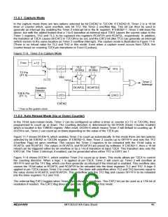
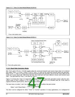
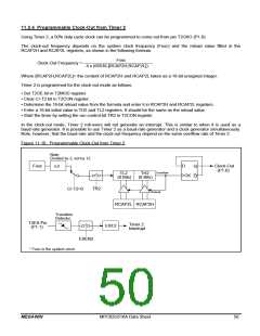
11.2.4 Programmable Clock-Out from Timer 2
Using Timer 2, a 50% duty cycle clock can be programmed to come out from pin T2CKO (P1.0).
The clock-out frequency depends on the system clock frequency (Fosc) and the reload value filled in the
RCAP2H and RCAP2L registers, as shown in the following formula:
Fosc
Clock-Out Frequency =
4 x (65536-[RCAP2H,RCAP2L])
Where [RCAP2H,RCAP2L]= the content of RCAP2H and RCAP2L taken as a 16-bit unsigned integer.
Timer 2 is programmed for the clock-out mode as follows:
• Set T2OE bit in T2MOD register.
• Clear C/-T2 bit in T2CON register.
• Determine the 16-bit reload value from the formula and enter it in RCAP2H and RCAP2L registers.
• Enter a 16-bit initial value in TH2 and TL2 registers. It should be the same as the reload value.
• Start the timer by setting the run control bit TR2 in T2CON register.
In the clock-out mode, Timer 2 roll-overs will not generate an interrupt. This is similar to when it is used as a
baud-rate generator. It is possible to use Timer 2 as a baud-rate generator and a clock generator simultaneously.
Note, however, that the baud-rate and the clock-out frequency depend on the same overflow rate of Timer 2.
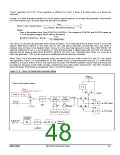
Figure 11-10. Programmable Clock-Out from Timer 2
Note:
Divided by 2, not by 12.
Fosc
D
Clock-Out
(P1.0)
Q
Q
2
Overflow
TL2
(8 Bits)
TH2
(8 Bits)
CK
TR2
C/-T2=0
Reload
RCAP2L RCAP2H
Transition
Detector
T2EX Pin
(P1.1)
Timer 2
Interrupt
EXF2
EXEN2
* Fosc is the system clock.
MEGAWIN
MPC82G516A Data Sheet
50

 MEGAWIN [ MEGAWIN TECHNOLOGY CO., LTD ]