“Timer” operation (C/-T2=0). Timer operation is different for Timer 2 when it is being used as a baud rate
generator.
Usually, as a timer it would increment at 1/12 the system clock frequency. As a baud rate generator, it increments
at 1/2 the system clock. Thus the baud rate formula is as follows:
Fosc
1
Mode 1 and 3 Baud Rates =
Where:
x
16
2 x ( 65536 - [RCAP2H,RCAP2L] )
Fosc is the system clock. And (RCAP2H, RCAP2L)= The content of RCAP2H and RCAP2L taken as
a 16-bit unsigned integer, which can be derived by:
Fosc
[RCAP2H,RCAP2L] = 65536 -
32 x Baud Rate
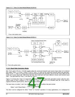
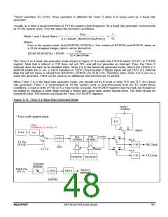
The Timer 2 as a baud rate generator mode shown in Figure 11-9 is valid only if RCLK and/or TCLK=1 in T2CON
register. Note that a rollover in TH2 does not set TF2, and will not generate an interrupt. Thus, the Timer 2
interrupt does not have to be disabled when Timer 2 is in the baud rate generator mode. Also if the EXEN2 (T2
external enable bit) is set, a 1-to-0 transition in T2EX (Timer/counter 2 trigger input) will set EXF2 (T2 external
flag) but will not cause a reload from (RCAP2H, RCAP2L) to (TH2,TL2). Therefore when Timer 2 is in use as a
baud rate generator, T2EX can be used as an additional external interrupt, if needed.
When Timer 2 is in the baud rate generator mode, one should not try to read or write TH2 and TL2. As a baud
rate generator, Timer 2 is incremented at 1/2 the system clock or asynchronously from pin T2; under these
conditions, a read or write of TH2 or TL2 may not be accurate. The RCAP2 registers may be read, but should not
be written to, because a write might overlap a reload and cause write and/or reload errors. The timer should be
turned off (clear TR2) before accessing the Timer 2 or RCAP2 registers.
Figure 11-9. Timer 2 in Baud Rate Generator Mode
Timer 1
Overflow
* Fosc is the system clock.
2
* Note:
Divided by 2, not by 12.
"0"
"1"
SMOD
Fosc
2
"0"
"1"
Overflow
TL2
(8 Bits)
TH2
(8 Bits)
"1" "0"
RCLK
T2 Pin
(P1.0)
16
16
RX Clock
TX Clock
TR2
"1" "0"
Reload
C/-T2
TCLK
RCAP2L RCAP2H
Transition
Detector
T2EX Pin
(P1.1)
Timer 2
Interrupt
EXF2
EXEN2
MEGAWIN
MPC82G516A Data Sheet
48

 MEGAWIN [ MEGAWIN TECHNOLOGY CO., LTD ]