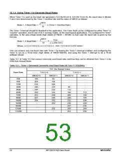
12.1.4 Using Timer 1 to Generate Baud Rates
When Timer 1 is used as the baud rate generator (T2CON.RCLK=0, T2CON.TCLK=0), the baud rates in Modes
1 and 3 are determined by the Timer 1 overflow rate and the value of SMOD as follows:
2SMOD
Mode 1, 3 Baud Rate =
x (Timer 1 Overflow Rate)
32
The Timer 1 interrupt should be disabled in this application. The Timer itself can be configured for either “timer” or
“counter” operation, and in any of its 3 running modes. In the most typical applications, it is configured for “timer”
operation, in the auto-reload mode (high nibble of TMOD = 0010B). In that case the baud rate is given by the
formula:
SMOD
2
Fosc
x
Mode 1, 3 Baud Rate =
32
n x (256-TH1)
(Note: T1X12 bit is in AUXR2 register.)
Where, n=12 if T1X12=0; n=1 if T1X12=1.
One can achieve very low baud rates with Timer 1 by leaving the Timer 1 interrupt enabled, and configuring the
Timer to run as a 16-bit timer (high nibble of TMOD=0001B), and using the Timer 1 interrupt to do a 16-bit
software reload.
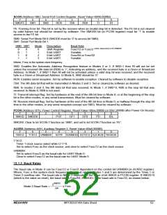
Table 12-1 & Table 12-2 list various commonly used baud rates and how they can be obtained from Timer 1 in its
8-Bit Auto-Reload Mode.
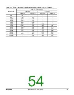
Table 12-1. Timer 1 Generated Commonly Used Baud Rates @ Fosc=11.0592MHz
TH1, the Reload Value
Baud Rate
T1X12=0
SMOD=0
T1X12=1
SMOD=1
SMOD=0
SMOD=1
300
600
160
208
232
240
244
250
252
253
254
-
64
160
208
224
232
244
248
250
252
253
-
-
-
-
-
1200
-
-
1800
64
-
2400
112
184
208
220
232
238
247
250
253
-
4800
112
160
184
208
220
238
244
250
7200
9600
14400
19200
38400
57600
115200
-
-
255
-
-
53
MPC82G516A Data Sheet
MEGAWIN

 MEGAWIN [ MEGAWIN TECHNOLOGY CO., LTD ]