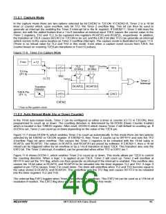
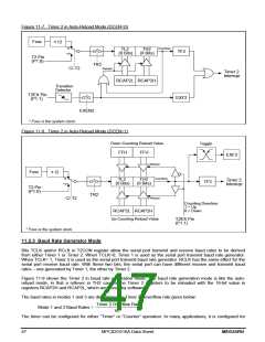
Figure 11-7. Timer 2 in Auto-Reload Mode (DCEN=0)
Fosc
12
"0"
"1"
Overflow
TL2
(8 Bits)
TH2
(8 Bits)
TF2
T2 Pin
(P1.0)
TR2
C/-T2
Reload
Timer 2
Interrupt
RCAP2L RCAP2H
Transition
Detector
T2EX Pin
(P1.1)
EXF2
EXEN2
* Fosc is the system clock.
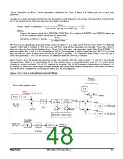
Figure 11-8. Timer 2 in Auto-Reload Mode (DCEN=1)
Down Counting Reload Value
Toggle
FFH
FFH
EXF2
Reload
Fosc
12
"0"
"1"
Overflow
TL2
(8 Bits)
TH2
(8 Bits)
Timer 2
Interrupt
TF2
T2 Pin
(P1.0)
TR2
Reload
C/-T2
Counting Direction:
1 = Up
0 = Down
RCAP2L RCAP2H
Up Counting Reload Value
T2EX Pin
(P1.1)
* Fosc is the system clock.
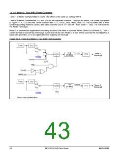
11.2.3 Baud Rate Generator Mode
Bits TCLK and/or RCLK in T2CON register allow the serial port transmit and receive baud rates to be derived
from either Timer 1 or Timer 2. When TCLK=0, Timer 1 is used as the serial port transmit baud rate generator.
When TCLK= 1, Timer 2 is used as the serial port transmit baud rate generator. RCLK has the same effect for the
serial port receive baud rate. With these two bits, the serial port can have different receive and transmit baud
rates – one generated by Timer 1, the other by Timer 2.
Figure 11-9 shows the Timer 2 in baud rate generation mode. The baud rate generation mode is like the auto-
reload mode, in that a rollover in TH2 causes the Timer 2 registers to be reloaded with the 16-bit value in
registers RCAP2H and RCAP2L, which are preset by software.
The baud rates in modes 1 and 3 are determined by Timer 2’s overflow rate given below:
Timer 2 Overflow Rate
Mode 1 and 3 Baud Rates =
16
The timer can be configured for either “Timer” or “Counter” operation. In many applications, it is configured for
47
MPC82G516A Data Sheet
MEGAWIN

 MEGAWIN [ MEGAWIN TECHNOLOGY CO., LTD ]