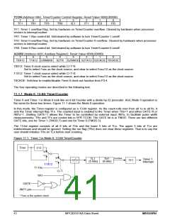
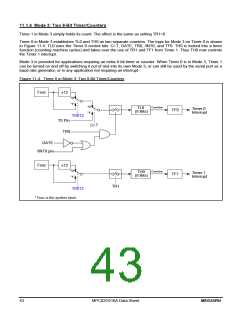
11.1.4 Mode 3: Two 8-Bit Timer/Counters
Timer 1 in Mode 3 simply holds its count. The effect is the same as setting TR1=0.
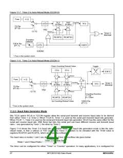
Timer 0 in Mode 3 establishes TL0 and TH0 as two separate counters. The logic for Mode 3 on Timer 0 is shown
in Figure 11-4. TL0 uses the Timer 0 control bits: C/-T, GATE, TR0, /INT0, and TF0. TH0 is locked into a timer
function (counting machine cycles) and takes over the use of TR1 and TF1 from Timer 1. Thus TH0 now controls
the Timer 1 interrupt.
Mode 3 is provided for applications requiring an extra 8-bit timer or counter. When Timer 0 is in Mode 3, Timer 1
can be turned on and off by switching it out of and into its own Mode 3, or can still be used by the serial port as a
baud rate generator, or in any application not requiring an interrupt.
Figure 11-4. Timer 0 in Mode 3: Two 8-Bit Timer/Counters
Fosc
12
"0"
"1"
"0"
"1"
Overflow
TL0
(8 Bits)
Timer 0
Interrupt
TF0
T0X12
T0 Pin
TR0
C/-T
GATE
/INT0 pin
Fosc
12
"0"
"1"
Overflow
TH0
(8 Bits)
Timer 1
Interrupt
TF1
TR1
T0X12
* Fosc is the system clock.
43
MPC82G516A Data Sheet
MEGAWIN

 MEGAWIN [ MEGAWIN TECHNOLOGY CO., LTD ]