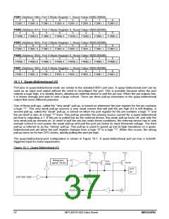
TCON (Address=88H, Timer/Counter Control Register, Reset Value=0000,0000B)
7
6
5
4
3
2
1
0
TF1
TR1
TF0
TR0
IE1
IT1
IE0
IT0
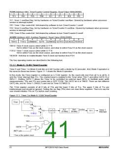
TF1: Timer 1 overflow Flag. Set by hardware on Timer/Counter overflow. Cleared by hardware when processor
vectors to interrupt routine.
TR1: Timer 1 Run control bit. Set/cleared by software to turn Timer/Counter 1 on/off.
TF0: Timer 0 overflow Flag. Set by hardware on Timer/Counter 0 overflow. Cleared by hardware when processor
vectors to interrupt routine.
TR0: Timer 0 Run control bit. Set/cleared by software to turn Timer/Counter 0 on/off.
AUXR2 (Address=A6H, Auxiliary Register2, Reset Value=0000,0000B)
7
6
5
4
3
2
1
0
T0X12
T1X12 URM0X6 S2TR S2SMOD S2TX12 S2CKOE T0CKOE
T0X12: Timer 0 clock source select while C/-T=0.
Set to select Fosc as the clock source, and clear to select Fosc/12 as the clock source.
T1X12: Timer 1 clock source select while C/-T=0.
Set to select Fosc as the clock source, and clear to select Fosc/12 as the clock source.
T0CKOE: Set/clear to enable/disable Timer 0 clock-out function from P3.4.
The four operating modes are described in the following text.
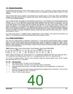
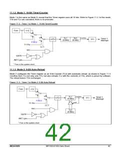
11.1.1 Mode 0: 13-Bit Timer/Counter
Timer 0 and Timer 1 in Mode 0 look like an 8-bit Counter with a divide-by-32 prescaler. And, Mode 0 operation is
the same for these two timers. Figure 11-1 shows the Mode 0 operation.
In this mode, the Timer register is configured as a 13-bit register. As the count rolls over from all 1s to all 0s, it
sets the Timer interrupt flag TFx. The counted input is enabled to the Timer when TRx=1 and either GATE=0 or
/INTx=1. (Setting GATE=1 allows the Timer to be controlled by external input /INTx, to facilitate pulse width
measurements). TRx and TFx are control bits in SFR TCON. The GATE bit is in TMOD. There are two different
GATE bits, one for Timer 1 (TMOD.7) and one for Timer 0 (TMOD.3).
The 13-bit register consists of all 8 bits of THx and the lower 5 bits of TLx. The upper 3 bits of TLx are
indeterminate and should be ignored. Setting the run flag (TRx) does not clear these registers. That is to say the
user should initialize THx an TLx before start counting.
Figure 11-1. Timer 1 in Mode 0: 13-Bit Timer/Counter
Fosc
12
"0"
"1"
"0"
"1"
Overflow
TL1
(5 Bits)
TH1
(8 Bits)
Timer 1
Interrupt
TF1
T1X12
T1 Pin
TR1
C/-T
GATE
/INT1 pin
* Fosc is the system clock.
41
MPC82G516A Data Sheet
MEGAWIN

 MEGAWIN [ MEGAWIN TECHNOLOGY CO., LTD ]