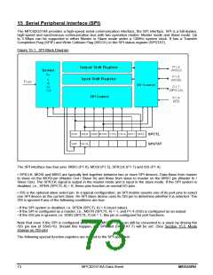
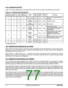
15.2 Configuring the SPI
Table 15-1 shows configuration for the master/slave modes as well as usages and directions for the modes.
Table 15-1. SPI Master and Slave Selection
/SS
-pin
MISO MOSI SPICLK
SPEN
SSIG
MSTR
(SPCTL.4)
Mode
Remarks
(SPCTL.6) (SPCTL.7)
-pin
-pin
-pin
P1.4~P1.7 are used as general
port pins.
0
1
1
X
0
0
X
0
1
X
0
0
SPI disabled input input
input
Salve
Selected as slave.
Not selected.
output input
(selected)
input
input
Slave
(not selected)
Hi-Z
input
Mode change to slave
Slave
(by mode
change)
if /SS pin is driven low, and MSTR
will be cleared to ‘0’ by H/W
automatically.
1
1
0
0
0
1
1 Î 0
output input
input
Hi-Z
MOSI and SPICLK are at high
impedance to avoid bus
contention when the Master is
idle.
Master
(idle)
Hi-Z
1
input
MOSI and SPICLK are push-pull
when the Master is active.
Master
(active)
output output
1
1
1
1
X
X
0
1
Slave
output input
input
Master
input output output
“X” means “don’t care”.
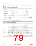
15.3 Additional Considerations for a Slave
When CPHA is 0, SSIG must be 0 and /SS pin must be negated and reasserted between each successive serial
byte transfer. Note the SPDAT register cannot be written while /SS pin is active (low), and the operation is
undefined if CPHA is 0 and SSIG is 1.
When CPHA is 1, SSIG may be 0 or 1. If SSIG=0, the /SS pin may remain active low between successive
transfers (can be tied low at all times). This format is sometimes preferred for use in systems having a single
fixed master and a single slave configuration.
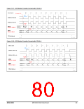
15.4 Additional Considerations for a Master
In SPI, transfers are always initiated by the master. If the SPI is enabled (SPEN=1) and selected as master,
writing to the SPI data register (SPDAT) by the master starts the SPI clock generator and data transfer. The data
will start to appear on MOSI about one half SPI bit-time to one SPI bit-time after data is written to SPDAT.
Before starting the transfer, the master may select a slave by driving the /SS pin of the corresponding device low.
Data written to the SPDAT register of the master is shifted out of MOSI pin of the master to the MOSI pin of the
slave. And, at the same time the data in SPDAT register of the selected slave is shifted out on MISO pin to the
MISO pin of the master.
After shifting one byte, the SPI clock generator stops, setting the transfer completion flag (SPIF) and an interrupt
will be created if the SPI interrupt is enabled. The two shift registers in the master CPU and slave CPU can be
considered as one distributed 16-bit circular shift register. When data is shifted from the master to the slave, data
is also shifted in the opposite direction simultaneously. This means that during one shift cycle, data in the master
and the slave are interchanged.
77
MPC82G516A Data Sheet
MEGAWIN

 MEGAWIN [ MEGAWIN TECHNOLOGY CO., LTD ]