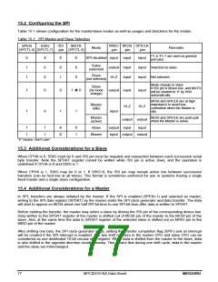
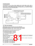
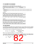
16 A/D Converter
The MPC82G516A has one 10-bit, 8-channel multiplexed inputs analog-to-digital converter, which is
implemented with successive approximation register (SAR) approach. Figure 16-1 shows the block diagram of
the A/D converter. The eight multiplexed analog inputs share input pins with Port 1. The multiplexed input has a
sample and hold circuit to feed the input analog voltage to the comparator input, and the output of the comparator
is fed to the SAR for successive approximating operation.
Figure 16-1. ADC Block Diagram
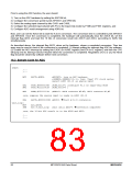
16.1 ADC Control Registers
ADCTL (Address=C5H, ADC Control Register, Reset Value=0000,0000B)
7
6
5
4
3
2
1
0
ADCON SPEED1 SPEED0 ADCI
ADCS
CHS2
CHS1
CHS0
ADCON: Clear to turn off the ADC block. Set to turn on the ADC block.
SPEED1 and SPEED0: A-to-D conversion speed selection bits.
(0,0): 1080 clock cycles are taken for a conversion.
(0,1): 540 clock cycles are taken for a conversion.
(1,0): 360 clock cycles are taken for a conversion.
(1,1): 270 clock cycles are taken for a conversion.
Note 1 clock cycle time is equal to 1/Fosc.
ADCS: ADC start bit.
Setting this bit by software starts an A/D conversion. On completion of the conversion, the ADC hardware will
clear ADCS and set the ADCI. ADCS cannot be cleared by software. A new conversion may not be started while
either ADCS or ADCI is high.
ADCI: ADC interrupt flag.
This flag is set when an A/D conversion is completed. An interrupt is invoked if it is enabled. The flag should be
cleared by software.
CHS2, CHS1 and CHS0: Multiplexed input channel selection bits.
(0,0,0): select AIN0 (P1.0) as the analog input
(0,0,1): select AIN1 (P1.1) as the analog input
(0,1,0): select AIN2 (P1.2) as the analog input
(0,1,1): select AIN3 (P1.3) as the analog input
(1,0,0): select AIN4 (P1.4) as the analog input
81
MPC82G516A Data Sheet
MEGAWIN

 MEGAWIN [ MEGAWIN TECHNOLOGY CO., LTD ]