8.2 Access Timing Stretching for Low-speed Memory
To access the low-speed external data memory, the timing-stretch mechanism is designed to control the access
timing of the “MOVX” instructions. The bits ALES1 and ALES0, in STRETCH register, control the stretching of
the setup time and hold time with respect to ALE negative edge. And, the bits RWS2, RWS1 and RWS0 control
the stretching of the read/write pulse width. The user should configure STRETCH register properly to conform to
the read/write requirements of the external data memory being used.
STRETCH (Address=8FH, Stretch Register, Reset Value=0010,0011B)
7
6
5
4
3
2
1
0
-
-
ALES1
ALES0
-
RWS2
RWS1
RWS0
{ALES1,ALES0} :
00: No stretch, the P0’s address setup/hold time to the following ALE falling edge is 1 clock cycle.
01: 1 clock stretched, the P0’s address setup/hold time to the following ALE falling edge is 2 clock cycles.
10: 2 clocks stretched, the P0’s address setup/hold time to the following ALE falling edge is 3 clock cycles.
11: 3 clocks stretched, the P0’s address setup/hold time to the following ALE falling edge is 4 clock cycles.
{RWS2,RWS1,RWS0} :
000: No stretch, the MOVX read/write pulse is 1 clock cycle.
001: 1 clock stretched, the MOVX read/write pulse is 2 clock cycles.
010: 2 clocks stretched, the MOVX read/write pulse is 3 clock cycles.
011: 3 clocks stretched, the MOVX read/write pulse is 4 clock cycles.
100: 4 clocks stretched, the MOVX read/write pulse is 5 clock cycles.
101: 5 clocks stretched, the MOVX read/write pulse is 6 clock cycles.
110: 6 clocks stretched, the MOVX read/write pulse is 7 clock cycles.
111: 7 clocks stretched, the MOVX read/write pulse is 8 clock cycles.
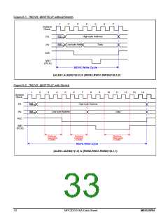
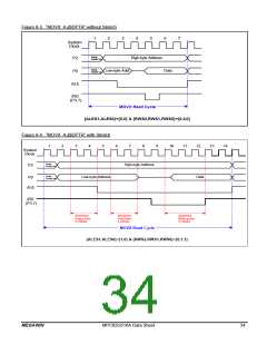
See the following timing waveforms for demonstration.
MEGAWIN
MPC82G516A Data Sheet
32

 MEGAWIN [ MEGAWIN TECHNOLOGY CO., LTD ]