10 I/O Port Structure and Operation
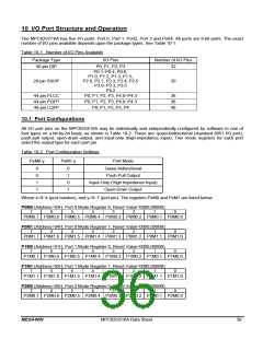
The MPC82G516A has five I/O ports: Port 0, Port 1, Port2, Port 3 and Port4. All ports are 8-bit ports. The exact
number of I/O pins available depends upon the package types. See Table 10-1.
Table 10-1. Number of I/O Pins Available
Package Type
40-pin DIP
I/O Pins
Number of I/O Pins
32
P0, P1, P2, P3
P0.1~P0.4, P0.6,
P1.0, P1.2, P1.3, P1.5,
P2.0, P2.1, P2.3, P2.4, P2.5
P3.0~P3.3, P3.5
28-pin SSOP
20
P4.2
44-pin PLCC
44-pin PQFP
48-pin LQFP
P0, P1, P2, P3, P4.0~P4.3
P0, P1, P2, P3, P4.0~P4.3
P0, P1, P2, P3, P4
36
36
40
10.1 Port Configurations
All I/O port pins on the MPC82G516A may be individually and independently configured by software to one of
four types on a bit-by-bit basis, as shown in Table 10-2. These are: quasi-bidirectional (standard 8051 I/O port),
push-pull output, open-drain output, and input-only (high-impedance input). Two mode registers for each port
select the output type for each port pin.
Table 10-2. Port Configuration Settings
PxM0.y
PxM1.y
Port Mode
Quasi-bidirectional
0
0
1
1
0
1
0
1
Push-Pull Output
Input-Only (High Impedance Input)
Open-Drain Output
Where x=0~4 (port number), and y=0~7 (port pin). The registers PxM0 and PxM1 are listed below.
P0M0 (Address=93H, Port 0 Mode Register 0, Reset Value=0000,0000B)
7
6
5
4
3
2
1
0
P0M0.7 P0M0.6 P0M0.5 P0M0.4 P0M0.3 P0M0.2 P0M0.1 P0M0.0
P0M1 (Address=94H, Port 0 Mode Register 1, Reset Value=0000,0000B)
7
6
5
4
3
2
1
0
P0M1.7 P0M1.6 P0M1.5 P0M1.4 P0M1.3 P0M1.2 P0M1.1 P0M1.0
P1M0 (Address=91H, Port 1 Mode Register 0, Reset Value=0000,0000B)
7
6
5
4
3
2
1
0
P1M0.7 P1M0.6 P1M0.5 P1M0.4 P1M0.3 P1M0.2 P1M0.1 P1M0.0
P1M1 (Address=92H, Port 1 Mode Register 1, Reset Value=0000,0000B)
7
6
5
4
3
2
1
0
P1M1.7 P1M1.6 P1M1.5 P1M1.4 P1M1.3 P1M1.2 P1M1.1 P1M1.0
P2M0 (Address=95H, Port 2 Mode Register 0, Reset Value=0000,0000B)
7
6
5
4
3
2
1
0
P2M0.7 P2M0.6 P2M0.5 P2M0.4 P2M0.3 P2M0.2 P2M0.1 P2M0.0
MEGAWIN
MPC82G516A Data Sheet
36

 MEGAWIN [ MEGAWIN TECHNOLOGY CO., LTD ]