MX29LV640BT/BB
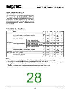
WRITE OPERATION STATUS
The device provides several bits to determine the status
of a write operation: Q2, Q3, Q5, Q6, Q7, and RY/BY#.
Table 5 and the following subsections describe the func-
tions of these bits. Q7, RY/BY#, and Q6 each offer a
method for determining whether a program or erase op-
eration is complete or in progress. These three bits are
discussed first.
Table 5. Write Operation Status
Status
Q7
Q6
Q5
Q3
Q2 RY/BY#
Note1
Note2
Byte/Word Program in Auto Program Algorithm
Auto Erase Algorithm
Q7
Toggle
Toggle
0
N/A
1
No
0
Toggle
0
1
0
0
Toggle
0
1
Erase Suspend Read
(Erase Suspended Sector)
No
Toggle
N/A Toggle
In Progress
Erase Suspended Mode
Erase Suspend Read
Data
Q7
Data Data Data Data
1
0
0
(Non-Erase Suspended Sector)
Erase Suspend Program
Toggle
Toggle
0
1
N/A N/A
Byte/Word Program in Auto Program Algorithm
Q7
N/A
1
No
Toggle
Exceeded
Time Limits Auto Erase Algorithm
0
Toggle
Toggle
1
1
Toggle
0
0
Erase Suspend Program
Q7
N/A N/A
Notes:
1. Performing successive read operations from the erase-suspended sector will cause Q2 to toggle.
2. Performing successive read operations from any address will cause Q6 to toggle.
3. Reading the byte address being programmed while in the erase-suspend program mode will indicate logic "1" at the
Q2 bit.
However, successive reads from the erase-suspended sector will cause Q2 to toggle.
P/N:PM1076
REV. 1.2, SEP. 07, 2005
28

 Macronix [ MACRONIX INTERNATIONAL ]