MX29LV640BT/BB
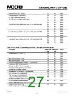
Number of erase block regions
2C
2D
58
5A
5C
5E
60
62
64
66
68
6A
6C
6E
70
72
74
76
78
0002
0007
Erase block region 1 information
[2E,2D] = # of blocks in region -1
[30, 2F] = size in multiples of 256-bytes
2E
0000
2F
0020
30
0000
31h
32h
33h
34h
35h
36h
37h
38h
39h
3Ah
3Bh
3Ch
007Eh
0000h
0000h
0001h
0000h
0000h
0000h
0000h
0000h
0000h
0000h
0000h
Erase Block Region 2 Information (refer to CFI publication 100)
Erase Block Region 3 Information (refer to CFI publication 100)
Erase Block Region 4 Information (refer to CFI publication 100)
Table 4-4. CFI Mode: Primary Vendor-Specific Extended Query Data Values
Description
Addressh Addressh
Datah
(x16)
40
(x8)
80
82
84
86
88
8A
8C
8E
90
92
94
96
98
9A
Query-unique ASCII string "PRI"
0050
0052
0049
0031
0031
0000
0002
0004
0001
0004
0000
0000
0000
00B5
41
42
Major version number, ASCII
43
Minor version number, ASCII
44
Address sensitive unlock (0=required, 1= not required)
Erase suspend (2= to read and write)
Sector protect (N= # of sectors/group)
Temporarysectorunprotect(1=supported)
Sector protect/unprotect scheme
45
46
47
48
49
SimultaneousR/Woperation(0=notsupported)
Burst mode type (0=not supported)
4A
4B
4C
4Dh
Page mode type (0=not supported)
ACC (Acceleration) Supply Minimum
00h=NotSupported,D7-D4:Volt,D3-D0:100mV
ACC (Acceleration) Supply Maximum
00h=NotSupported,D7-D4:Volt,D3-D0:100mV
Top/Bottom Boot Sector Flag
4Eh
4Fh
9C
9E
00C5
0002h/
0003h
02h=Bottom Boot Device, 03h=Top Boot Device
P/N:PM1076
REV. 1.2, SEP. 07, 2005
27

 Macronix [ MACRONIX INTERNATIONAL ]