MX29LV640BT/BB
mode, so that all sectors are unprotected after chip
unprotect is completed to incorporate any changes in the
code.It is recommended to protect all sectors before ac-
tivating chip unprotect mode.
unconnected; inconsistent behavior of the device may
result.
TEMPORARY SECTOR GROUP UNPROTECT
OPERATION
To activate this mode, the programming equipment must
force VID on control pin OE# and address pin A9. The
CE# pins must be set at VIL. Pins A6 must be set to
VIH.(seeTable 2) Refer to chip unprotect algorithm and
waveform for the chip unprotect algorithm. The unprotect
mechanism begins on the falling edge of the WE# pulse
and is terminated on the rising edge.
This feature allows temporary unprotect of previously
protected sector to change data in-system.The Tempo-
rary Sector Unprotect mode is activated by setting the
RESET# pin toVID(11.5V-12.5V). During this mode, for-
merly protected sectors can be programmed or erased
as unprotect sector. Once VID is remove from the RE-
SET# pin, all the previously protected sectors are pro-
tected again.
MX29LV640BT/BB also provides another method.Which
requires VID on the RESET# only. This method can be
implemented either in-system or via programming equip-
ment. This method uses standard microprocessor bus
cycle timing.
SILICON ID READ OPERATION
It is also possible to determine if the chip is unprotect in
the system by writing the Read Silicon ID command.
Performing a read operation with A1=VIH, it will produce
00H at data outputs (Q0-Q7) for an unprotect sector.It is
noted that all sectors are unprotected after the chip
unprotect algorithm is completed.
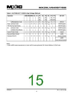
Flash memories are intended for use in applications where
the local CPU alters memory contents. As such, manu-
facturer and device codes must be accessible while the
device resides in the target system. PROM program-
mers typically access signature codes by raising A9 to
a high voltage. However, multiplexing high voltage onto
address lines is not generally desired system design prac-
tice.
WRITE PROTECT (WP#)
MX29LV640BT/BB provides hardware method to access
the silicon ID read operation.Which method requiresVID
on A9 pin, VIL on CE#, OE#, A6, and A1 pins. Which
applyVIL on A0 pin, the device will output MXIC's manu-
facture code of C2H. Which apply VIH on A0 pin, the
device will output MX29LV640BT/BB device code of C9H/
CBH.
The write protect function provides a hardware method
to protect boot sectors without using VID.
If the system asserts VIL on the WP#/ACC pin, the de-
vice disables program and erase functions in the two "out-
ermost" 8 Kbyte boot sectors independently of whether
those sectors were protected or unprotect using the
method described in Sector/Sector Group Protection and
Chip Unprotect". The two outermost 8 Kbyte boot sec-
tors are the two sectors containing the lowest addresses
in a bottom-boot-configured device, or the two sectors
containing the highest addresses in a top-boot-config-
ured device.
VERIFY SECTOR GROUP PROTECT STATUS
OPERATION
MX29LV640BT/BB provides hardware method for sector
group protect status verify. Which method requires VID
on A9 pin, VIH on WE# and A1 pins, VIL on CE#, OE#,
A6, and A0 pins, and sector address on A16 to A21 pins.
Which the identified sector is protected, the device will
output 01H. Which the identified sector is not protect,
the device will output 00H.
If the system asserts VIH on the WP#/ACC pin, the de-
vice reverts to whether the two outermost 8K Byte boot
sectors were last set to be protected or unprotect. That
is, sector protection or unprotection for these two sectors
depends on whether they were last protected or unprotect
using the method described in "Sector/Sector Group Pro-
tection and Chip Unprotect".
DATA PROTECTION
Note that the WP#/ACC pin must not be left floating or
The MX29LV640BT/BB is designed to offer protection
P/N:PM1076
REV. 1.2, SEP. 07, 2005
18

 Macronix [ MACRONIX INTERNATIONAL ]