MX29LV640BT/BB
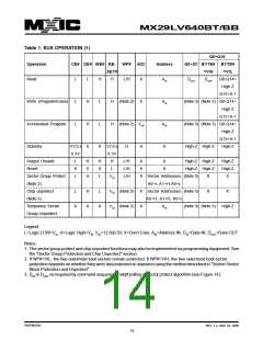
Table 1. BUS OPERATION (1)
Q8~Q15
Operation
CE# OE# WE# RE-
WP# ACC
Address
Q0~Q7 BYTE# BYTE#
SET#
=VIH
=VIL
Read
L
L
L
L
H
H
X
H
L
H
L/H
X
X
AIN
DOUT
DOUT
Q8-Q14=
High Z
Q15=A-1
Write (Program/Erase)
Accelerated Program
Standby
H
H
(Note 2)
AIN
AIN
X
(Note 3) (Note 3) Q8-Q14=
High Z
Q15=A-1
L
(Note 2) VHH
(Note 3) (Note 3) Q8-Q14=
High Z
Q15=A-1
VCC±
X
VCC±
0.3V
H
H
H
High-Z High-Z
High-Z
0.3V
Output Disable
Reset
L
X
L
H
X
H
H
X
L
L/H
L/H
L/H
X
X
X
X
X
High-Z High-Z
High-Z High-Z
High-Z
High-Z
X
L
Sector Group Protect
(Note 2)
VID
Sector Addresses, (Note 3)
A6=L,A1=H,A0=L
X
Chip unprotect
(Note 2)
L
H
X
L
VID (Note 2)
VID (Note 2)
X
X
Sector Addresses, (Note 3)
A6=H, A1=H, A0=L
X
X
Temporary Sector
Group Unprotect
X
X
AIN
(Note 3) (Note 3)
High-Z
Legend:
L=Logic LOW=VIL, H=Logic High=VIH, VID=12.0±0.5V, X=Don't Care, AIN=Address IN, DIN=Data IN, DOUT=Data OUT
Notes:
1. The sector group protect and chip unprotect functions may also be implemented via programming equipment. See
the "Sector Group Protection and Chip Unprotect" section.
2. If WP#=VIL, the two outermost boot sectors remain protected. If WP#=VIH, the two outermost boot sector
protection depends on whether they were last protected or unprotect using the method described in "Sector/ Sector
Block Protection and Unprotect".
3. DIN or DOUT as required by command sequence, Data# polling or sector protect algorithm (see Figure 14).
P/N:PM1076
REV. 1.2, SEP. 07, 2005
14

 Macronix [ MACRONIX INTERNATIONAL ]