MX29LV640BT/BB
against accidental erasure or programming caused by
spurious system level signals that may exist during power
transition. During power up the device automatically re-
sets the state machine in the Read mode. In addition,
with its control register architecture, alteration of the
memory contents only occurs after successful comple-
tion of specific command sequences. The device also
incorporates several features to prevent inadvertent write
cycles resulting fromVCC power-up and power-down tran-
sition or system noise.
is removed from the device. On power-up, or following a
hardware reset, the device reverts to sending command
to sector SA0.
LOW VCC WRITE INHIBIT
When VCC is less than VLKO the device does not ac-
cept any write cycles. This protects data during VCC
power-up and power-down.The command register and
all internal program/erase circuits are disabled, and the
device resets. Subsequent writes are ignored until VCC
is greater thanVLKO. The system must provide the proper
signals to the control pins to prevent unintentional write
whenVCC is greater thanVLKO.
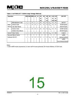
SECURED SILICON SECTOR
The MX29LV640BT/BB features a OTP memory region
where the system may access through a command se-
quence to create a permanent part identification as so
called Electronic Serial Number (ESN) in the device.
Once this region is programmed, any further modifica-
tion on the region is impossible.The secured silicon sector
is a 128 words in length, and uses a Secured Silicon
Sector Indicator Bit (Q7) to indicate whether or not the
Secured Silicon Sector is locked when shipped from the
factory. This bit is permanently set at the factory and
cannot be changed, which prevent duplication of a fac-
tory locked part. This ensures the security of the ESN
once the product is shipped to the field.
WRITE PULSE "GLITCH" PROTECTION
Noise pulses of less than 5ns (typical) on CE# or WE#
will not initiate a write cycle.
LOGICAL INHIBIT
Writing is inhibited by holding any one of OE# = VIL,
CE# = VIH or WE# = VIH. To initiate a write cycle CE#
and WE# must be a logical zero while OE# is a logical
one.
The MX29LV640BT/BB offers the device with Secured
Silicon Sector either factory locked or customer lock-
able. The factory-locked version is always protected
when shipped from the factory , and has the Secured
Silicon Sector Indicator Bit permanently set to a "1".
The customer-lockable version is shipped with the Se-
cured Silicon Sector unprotected, allowing customers to
utilize that sector in any form they prefer.The customer-
lockable version has the secured sector Indicator Bit
permanently set to a "0". Therefore, the Secured Silicon
Sector Indicator Bit prevents customer, lockable device
from being used to replace devices that are factory locked.
POWER-UP SEQUENCE
The MX29LV640BT/BB powers up in the Read only mode.
In addition, the memory contents may only be altered
after successful completion of the predefined command
sequences.
POWER-UP WRITE INHIBIT
The system access the Secured Silicon Sector through
a command sequence (refer to "Enter Secured Silicon/
Exit Secured Silicon Sector command Sequence). After
the system has written the Enter Secured Silicon Sector
command sequence, it may read the Secured Silicon
Sector by using the address normally occupied by the
last sector SA134 (for MX29LV640BT) or first sector SA0
(for MX29LV640BB). Once entry the Secured Silicon
Sector the operation of boot sectors is disabled but the
operation of main sectors is as normally. This mode of
operation continues until the system issues the Exit Se-
cured Silicon Sector command sequence, or until power
If WE#=CE#=VIL and OE#=VIH during power up, the
device does not accept commands on the rising edge of
WE#. The internal state machine is automatically reset
to the read mode on power-up.
POWER SUPPLY DE COUPLING
In order to reduce power switching effect, each device
should have a 0.1uF ceramic capacitor connected be-
tween itsVCC and GND.
P/N:PM1076
REV. 1.2, SEP. 07, 2005
19

 Macronix [ MACRONIX INTERNATIONAL ]