Step-Up Converter
for Handheld Applications
The IC is designed to operate with the input voltage
range straddling its output voltage set point. Two tech-
niques are used to accomplish this. The first technique is
to activate ATM if the input voltage exceeds 95% of the
output set point; see the Automatic Track Mode (ATM)
section. The second technique is automatic frequency
adjustment.
•ꢀ In track and ATM, current is limited to prevent
excessive inrush current during soft-start and to
protect against overload conditions. If the die tem-
perature exceeds +165°C in track/ATM, the switch
turns off until the die temperature has cooled to
+145NC.
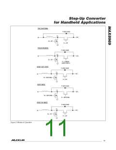
•ꢀ In boost mode, during each 3MHz switching cycle,
if the inductor current exceeds 2.6A, the n-channel
MOSFET is shut off and the p-channel MOSFET is
switched on. The end result is that LX_ current is
regulated to 2.6A or less. A 2.6A inductor current
is a large enough current to guarantee a 1A output
load current under all intended operating conditions.
The IC can operate indefinitely while regulating the
inductor current to 2.6A or less.
Automatic Track Mode (ATM)
ATM is entered when an internal comparator signals that
the input voltage has exceeded the ATM threshold. The
ATM threshold is 95% of the output voltage target. At this
point, the IC enters ATM, with the pMOS switch turned
on, regardless of the status of TREN. Note that EN must
be high to enable ATM mode. This behavior is summa-
rized in Table 1.
However, if a short circuit or extremely heavy load is
applied to the output, the output voltage decreases since
the inductor current is limited to 2.6A.
Automatic Frequency Adjustment
Automatic frequency adjustment is used to maintain
stability if the input voltage is above 80% and below
95% of the output set point. Frequency adjustment is
required because the n-channel has a minimum on-time
of approximately 60ns. At 3MHz, this would lead to the
p-channel having a maximum duty factor of 82%. With
an input voltage more than 82% of the output set point,
the p-channel’s duty factor must be increased by reduc-
ing operating frequency either through cycle skipping
or adjusting the clock’s frequency. The IC adjusts its
clock frequency rather than simply skipping cycles. This
adjustment is done in two steps. The first step occurs if
the input voltage exceeds approximately 83% of the out-
put voltage and reduces clock speed to approximately
1.6MHz. The second step occurs if the input voltage is
greater than output voltage less 460mV. If this condition
is met, clock frequency is reduced to approximately
1MHz. Frequency adjustment allows the converter to
operate at a known frequency under all conditions.
If the output voltage decreases to less than 72% of the
regulation voltage target (i.e., 2.8V with V
of
OUT_TARGET
3.7V), a short circuit is assumed, and the IC returns to
the shutdown state. The IC then attempts to start up if the
output short is removed. Even if the output short persists
indefinitely, the IC thermal protection ensures that the die
is not damaged.
True Shutdown
During operation in boost mode, the p-channel MOSFET
prevents current from flowing from OUT_ to LX_. In all
other modes of operation, it is desirable to block current
flowing from LX_ to OUT_. True Shutdown prevents current
from flowing from LX_ to OUT_ while the IC is shut down
by reversing the internal body diode of the p-channel
MOSFET. This feature is also active during track/ATM to
allow current limit to function as anticipated.
Upon leaving boost mode, the p-channel MOSFET
continues to prevent current from flowing from OUT_ to
LX_ until OUT_ and IN are approximately the same volt-
age. After this condition has been met, track/ATM and
shutdown operate normally.
Fault Protection
In track, ATM, and boost modes, the IC has protection
against overload and overheating.
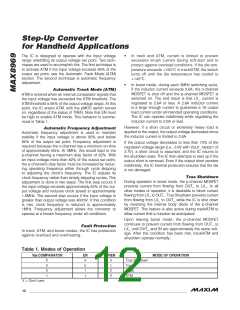
Table 1. Modes of Operation
V
IN
COMPARATOR
EN
TREN
MODE OF OPERATION
X
X
0
1
0
0
1
X
X
True Shutdown
Track
0
1
Boost
1
ATM
X = Don't care.
12 _____________________________________________________________________________________

 MAXIM [ MAXIM INTEGRATED PRODUCTS ]