Ultra-Efficient Charge Pumps for
Six White/RGB LEDs in 3mm x 3mm Thin QFN
2
used. Figure 2 shows a timing diagram for the I C pro-
Detailed Description
tocol. The MAX8647 is a slave-only device, relying
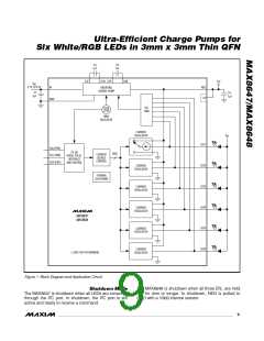
The MAX8647/MAX8648 have an inverting charge
upon a master to generate a clock signal. The master
pump and six current regulators capable of 24mA each
(typically a microprocessor) initiates data transfer on
to drive six white LEDs or two sets of RGB LEDs. The
the bus and generates SCL to permit data transfer. A
current regulators are matched to within 0.4% (typ)
master device communicates with the MAX8647 by
providing uniform white LED brightness for LCD back-
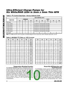
transmitting the proper 8-bit address (0x9A) followed
light applications. To maximize efficiency, the current
by the 8-bit control byte. Each 8-bit control byte con-
regulators operate with as little as 0.15V voltage drop.
sists of a 3-bit command code and 5 bits of data (Table
Individual white LED current regulators conduct current
to GND or NEG to extend usable battery life. In the
case of mismatched forward voltage of white LEDs,
only the white LEDs requiring higher voltage are
switched to pull current to NEG instead of GND, further
raising efficiency and reducing battery current drain.
1). Each transmit sequence is framed by a START (A)
condition and a STOP (L) condition (Figure 2). Each
word transmitted over the bus is 8 bits long and is
always followed by an ACKNOWLEDGE CLOCK
PULSE (K). The power-on default settings for D4 to D0
are all 0, which indicates that all LED_ are off.
Current-Regulator Switchover
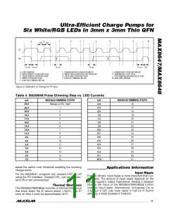
Serial-Pulse Dimming Control (MAX8648)
When the LEDs are enabled by driving EN_ high, the
MAX8648 ramps LED current to 24mA. Dim the LEDs
by pulsing EN_ low (1µs to 500µs pulse width). Each
pulse reduces the LED current based on the LED dim-
ming table, Table 3. After the current reaches 0.1mA,
the next pulse restores the current to 24mA. Figure 3
shows a timing diagram for EN_. ENA controls LED1,
LED2, and LED3. ENB controls LED4 and LED5. ENC
controls LED6.
When V is higher than the forward voltage of the
IN
white LED plus the 0.15V headroom of the current regu-
lator, the LED current returns through GND. If this con-
dition is satisfied for all six white LEDs, the charge
pump remains inactive. When the input voltage drops
so that the current-regulator headroom cannot be main-
tained for any of the individual white LEDs, the inverting
charge pump activates and generates a voltage on the
7/MAX648
NEG pin that is no greater than 5V below V . Each cur-
IN
rent regulator contains circuitry that detects when it is
in dropout and switches that current-regulator return
path from GND to NEG. Since this is done on an LED-
by-LED basis, the LED current is switched for only the
individual LED requiring higher voltage, thus minimizing
power consumption.
If dimming control is not required, EN_ work as simple
100% brightness or off controls. Drive EN_ high to enable
the LEDs, or drive EN_ low to disable. The IC is shut-
down when all three EN_ are low for 4ms or longer.
Table 1. Internal PWM Duty Cycle vs. LED
Set Current
Low LED Current Levels
The MAX8647/MAX8648 internally generate a PWM sig-
nal to obtain higher resolution at lower currents. See
Single-Wire Pulse Dimming in the Typical Operating
I
DUTY CYCLE
(n/16)
I
DUTY CYCLE
(n/16)
LED
LED
(mA)
(mA)
Characteristics section. As the I
setting is below
LED
6.4
5.6
4.8
4.0
3.2
2.8
2.4
2.0
1.6
1.4
16
14
12
10
16
14
12
10
16
14
1.2
1.0
0.8
0.7
0.6
0.5
0.4
0.3
0.2
0.1
12
10
8
6.4mA, the IC adjusts not only I
DC current, but the
LED
duty cycle is controlled by the PWM signal. The fre-
quency of the PWM dimming signal is set at 1kHz with
a minimum duty cycle of 1/16 to avoid the LED flicking
effect to human eyes. Table 1 shows the current level
and the corresponding duty cycle.
7
6
5
2
I C Interface (MAX8647)
4
2
An I C 2-wire serial interface is provided on the
3
MAX8647 to control the LEDs. The serial interface
consists of a serial-data line (SDA) and a serial-clock
2
2
1
line (SCL). Standard I C write-byte commands are
8
_______________________________________________________________________________________

 MAXIM [ MAXIM INTEGRATED PRODUCTS ]