Ultra-Efficient Charge Pumps for
Six White/RGB LEDs in 3mm x 3mm Thin QFN
0
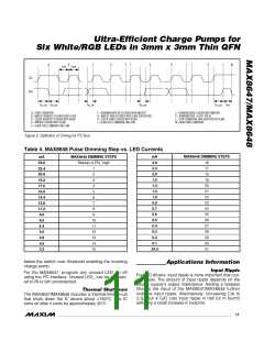
1
2
3
4
5
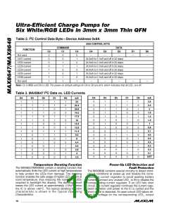
26
27
28
29
30
31
INITIAL t
> 120μs
HI
EN
_
t
SHDN
4ms
t
t
HI
> 1μs
LO
24mA
24mA
22.4
1μs TO 500μs
22.4
20.8
19.2
17.6
16.0
I
LED_
0.6
0.5
0.4
0.3
0.2
0.1mA
0mA
0mA
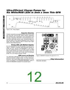
Figure 3. EN_ Timing Diagram
Capacitor Selection
Ceramic capacitors are recommended due to their small
size, low cost, and low ESR. Select ceramic capacitors
that maintain their capacitance over temperature and
DC bias. Capacitors with X5R or X7R temperature char-
acteristics generally perform well. Recommended val-
ues are shown in the Typical Operating Circuit. Using a
larger value input capacitor helps to reduce input ripple
(see the Input Ripple section).
7/MAX648
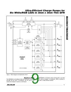
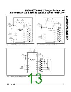
Driving LEDs with Multiple Supplies
It is not necessary for the LED anodes to connect to IN.
Figure 7 shows an example using separate supplies to
power the LED_ groups of the MAX8648. In this exam-
ple, the voltage source (V1) provides power for RGB
LEDs (LED1, LED2, and LED3). V2 provides power for
backlight LEDs (LED4 and LED5), and V3 provides
power for a red charge indicator (LED6).
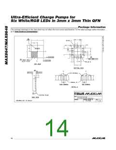
PCB Layout and Routing
The MAX8647/MAX8648 have a high-frequency,
switched-capacitor voltage inverter. For best circuit per-
formance, use a solid copper plane and place C1–C4 as
close as possible to the MAX8647/MAX8648. Figure 4
shows the MAX8648 evaluation kit example layout.
Figure 4. MAX8648 Evaluation Kit Layout for C1–C4
Chip Information
PROCESS: BiCMOS
12 ______________________________________________________________________________________

 MAXIM [ MAXIM INTEGRATED PRODUCTS ]