Ultra-Efficient Charge Pumps for
Six White/RGB LEDs in 3mm x 3mm Thin QFN
7/MAX648
A
B
C
D
E
F
G
H
I
J
K
L
M
t
t
HIGH
LOW
SCL
SDA
t
t
t
t
t
t
BUF
SU_STA
HD_STA
SU_DAT
HD_DAT
SU_STO
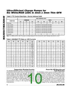
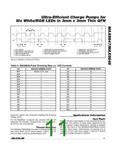
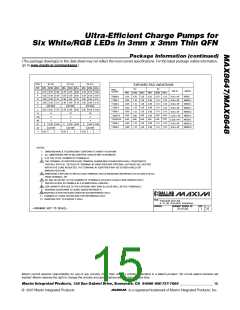
A = START CONDITION
F = ACKNOWLEDGE BIT CLOCKED INTO MASTER
G = MSB OF DATA CLOCKED INTO SLAVE (OP/SUS BIT)
H = LSB OF DATA CLOCKED INTO SLAVE
J = ACKNOWLEDGE CLOCKED INTO MASTER
K = ACKNOWLEDGE CLOCK PULSE
L = STOP CONDITION, DATA EXECUTED BY SLAVE
M = NEW START CONDITION
B = MSB OF ADDRESS CLOCKED INTO SLAVE
C = LSB OF ADDRESS CLOCKED INTO SLAVE
D = R/W BIT CLOCKED INTO SLAVE
I = SLAVE PULLS SMBDATA LINE LOW
E = SLAVE PULLS SMBDATA LINE LOW
2
Figure 2. Definition of Timing for I C Bus
Table 4. MAX8648 Pulse Dimming Step vs. LED Currents
mA
2.8
2.4
2.0
1.6
1.4
1.2
1.0
0.8
0.7
0.6
0.5
0.4
0.3
0.2
0.1
24.0
MAX8648 DIMMING STEPS
mA
24.0
22.4
20.8
19.2
17.6
16.0
14.4
12.8
11.2
9.6
MAX8648 DIMMING STEPS
16
17
18
19
20
21
22
23
24
25
26
27
28
29
30
31
Startup or EN_ high
1
2
3
4
5
6
7
8
9
8.0
10
11
12
13
14
15
6.4
5.6
4.8
4.0
3.2
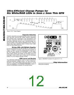
below the switch over threshold enabling the inverting
charge pump.
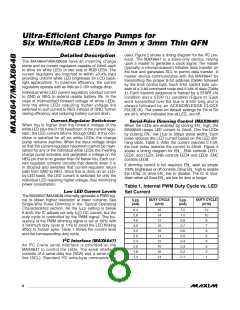
Applications Information
Input Ripple
For the MAX8647, program any unused LED_ to off
For LED drivers, input ripple is more important than out-
put ripple. The amount of input ripple depends on the
source supply’s output impedance. Adding a lowpass
filter to the input of the MAX8647/MAX8648 further
2
using the I C interface. Unused LED_ can be connect-
ed to IN or left unconnected.
Thermal Shutdown
The MAX8647/MAX8648 includes a thermal-limit circuit
that shuts down the IC above about +160°C. The IC
turns on after it cools by approximately 20°C.
reduces input ripple. Alternatively, increasing C to
IN
2.2µF (or 4.7µF) cuts input ripple in half (or in fourth)
with only a small increase in footprint.
______________________________________________________________________________________ 11

 MAXIM [ MAXIM INTEGRATED PRODUCTS ]