Ultra-Efficient Charge Pumps for
Six White/RGB LEDs in 3mm x 3mm Thin QFN
7/MAX648
Pin Description
PIN
NAME
FUNCTION
MAX8647 MAX8648
Supply Voltage Input. The input voltage range is 2.7V to 5.5V. Bypass IN to GND with a
1µF ceramic capacitor as close as possible to the IC. IN is high impedance during
shutdown. Connect IN to the anodes of all the LEDs.
1
1
IN
Ground. Connect GND to system ground and the input bypass capacitor as close as
possible to the IC.
2
3
4
5
6
2
3
4
5
6
GND
C1P
C2P
C2N
C1N
Transfer Capacitor 1 Positive Connection. Connect a 1µF ceramic capacitor from C1P
to C1N.
Transfer Capacitor 2 Positive Connection. Connect a 1µF ceramic capacitor from C2P
to C2N.
Transfer Capacitor 2 Negative Connection. Connect a 1µF ceramic capacitor from C2P
to C2N. An internal 10kΩ resistor pulls C2N to GND during shutdown.
Transfer Capacitor 1 Negative Connection. Connect a 1µF ceramic capacitor from C1P
to C1N.
Charge-Pump Negative Output. Connect a 1µF ceramic capacitor from NEG to GND. In
shutdown, an internal 10kΩ resistor pulls NEG to GND. Connect the exposed paddle to
NEG directly under the IC.
7
7
NEG
LED Current Regulators. Current flowing into LED_ is based on the internal registers.
Connect LED_ to the cathodes of the external LEDs. LED_ is high impedance during
shutdown. For the MAX8647, program any unused LED_ to off and LED_ can be
shorted to ground or left unconnected. For the MAX8648, short any unused LED_ to IN
prior to power-up to disable the corresponding current regulator.
8–13
8–13
LED6–LED1
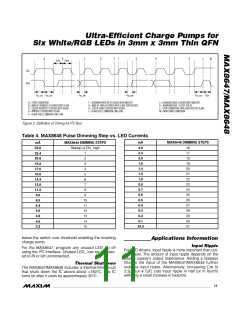
2
14
15
—
—
SDA
SCL
I C Data Input. Data is read on the rising edge of SCL.
2
I C Clock Input. Data is read on the rising edge of SCL.
Logic-Input Supply Voltage. Connect to the supply voltage driving SDA and SCL.
16
—
V
DD
Bypass V
to GND with a 0.1µF ceramic capacitor.
DD
Enable and Serial-Pulse Dimming Control. ENA controls LED1, LED2, and LED3. ENB
controls LED4 and LED5. ENC controls LED6. Drive EN_ logic-high to turn on the IC
and enable the corresponding LED_ at 24mA each. Drive an individual EN_ logic-low
for greater than 4ms to turn off the corresponding-current regulators or drive all three
EN_ low to place the IC in shutdown. See the Serial-Pulse Dimming Control (MAX8648)
section.
—
—
14, 15, 16 ENC, ENB, ENA
—
EP
Exposed Paddle. Connect to NEG.
_______________________________________________________________________________________
7

 MAXIM [ MAXIM INTEGRATED PRODUCTS ]