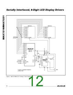
S e ria lly In t e rfa c e d , 8 -Dig it LED Dis p la y Drive rs
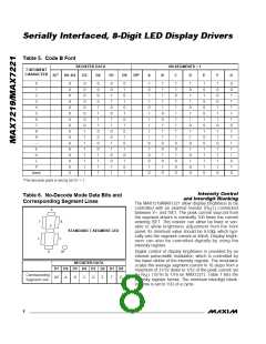
Table 5. Code B Font
REGISTER DATA
ON SEGMENTS = 1
7-SEGMENT
CHARACTER
D7* D6–D4
D3
D2
D1
D0
DP*
A
B
C
D
E
F
G
0
X
X
X
X
X
X
X
X
X
X
X
X
X
X
X
X
0
0
0
0
0
0
0
0
1
1
1
1
1
1
1
1
0
0
0
0
1
1
1
1
0
0
0
0
1
1
1
1
0
0
1
1
0
0
1
1
0
0
1
1
0
0
1
1
0
1
0
1
0
1
0
1
0
1
0
1
0
1
0
1
1
0
1
1
0
1
1
1
1
1
0
1
0
0
1
0
1
1
1
1
1
0
0
1
1
1
0
0
1
0
1
0
1
1
0
1
1
1
1
1
1
1
0
0
1
0
0
0
1
0
1
1
0
1
1
0
1
1
0
1
0
1
0
0
1
0
1
0
0
0
1
0
1
0
0
1
1
1
1
0
1
0
0
0
1
1
1
0
1
1
0
1
1
1
1
0
0
0
1
1
1
1
1
0
1
1
1
1
1
0
1
0
1
2
3
4
5
6
7
8
9
9/MAX721
—
E
H
L
P
blank
*The decimal point is set by bit D7 = 1
In t e n s it y Co n t ro l
a n d In t e rd ig it Bla n k in g
The MAX7219/MAX7221 allow display brightness to be
controlled with an external resistor (R ) connected
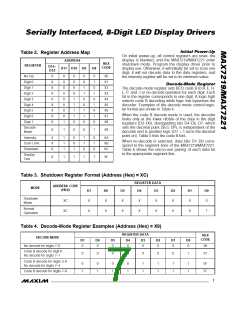
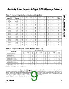
Table 6. No-Decode Mode Data Bits and
Corresponding Segment Lines
SET
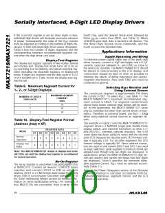
A
between V+ and ISET. The peak current sourced from
the segment drivers is nominally 100 times the current
entering ISET. This resistor can either be fixed or vari-
a b le to a llow b rig htne s s a d jus tme nt from the front
panel. Its minimum value should be 9.53Ω, which typi-
cally sets the segment current at 40mA. Display bright-
ne s s c a n a ls o b e c ontrolle d d ig ita lly b y us ing the
intensity register.
F
B
G
STANDARD 7-SEGMENT LED
E
C
D
DP
Digital control of display brightness is provided by an
internal pulse-width modulator, which is controlled by
the lower nibble of the intensity register. The modulator
scales the average segment current in 16 steps from a
maximum of 31/32 down to 1/32 of the peak current set
REGISTER DATA
D7 D6 D5 D4 D3 D2 D1 D0
Corresponding
Segment Line
by R
(15/16 to 1/16 on MAX7221). Table 7 lists the
SET
DP
A
B
C
D
E
F
G
intensity register format. The minimum interdigit blank-
ing time is set to 1/32 of a cycle.
8
_______________________________________________________________________________________

 MAXIM [ MAXIM INTEGRATED PRODUCTS ]