S e ria lly In t e rfa c e d , 8 -Dig it LED Dis p la y Drive rs
9/MAX721
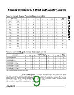
______________________________________________________________P in De s c rip t io n
PIN
NAME
FUNCTION
1
DIN
Serial-Data Input. Data is loaded into the internal 16-bit shift register on CLK’s rising edge.
Eight-Digit Drive Lines that sink current from the display common cathode. The MAX7219 pulls
the digit outputs to V+ when turned off. The MAX7221’s digit drivers are high-impedance when
turned off.
2, 3, 5–8,
10, 11
DIG 0–DIG 7
GND
4, 9
Ground (both GND pins must be connected)
LOAD
(MAX7219)
Load-Data Input. The last 16 bits of serial data are latched on LOAD’s rising edge.
12
CS
(MAX7221)
Chip-Select Input. Serial data is loaded into the shift register while CS is low. The last 16 bits of
serial data are latched on CS’s rising edge.
Serial-Clock Input. 10MHz maximum rate. On CLK’s rising edge, data is shifted into the inter-
nal shift register. On CLK’s falling edge, data is clocked out of DOUT. On the MAX7221, the
CLK input is active only while CS is low.
13
CLK
Seven Segment Drives and Decimal Point Drive that source current to the display. On the
MAX7219, when a segment driver is turned off it is pulled to GND. The MAX7221 segment dri-
vers are high-impedance when turned off.
14–17,
20–23
SEG A–SEG G,
DP
Connect to V through a resistor (R
) to set the peak segment current (Refer to Selecting
DD
SET
18
19
24
ISET
V+
R
Resistor section).
SET
Positive Supply Voltage. Connect to +5V.
Serial-Data Output. The data into DIN is valid at DOUT 16.5 clock cycles later. This pin is used
to daisy-chain several MAX7219/MAX7221’s and is never high-impedance.
DOUT
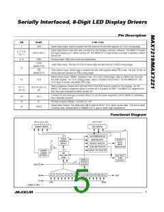
_________________________________________________________Fu n c t io n a l Dia g ra m
DIG 0–DIG 7
SEG A–SEG G, DP
SEGMENT DRIVERS
DIGIT DRIVERS
8
8
SHUTDOWN REGISTER
MODE REGISTER
CODE B
ROM WITH
BYPASS
INTENSITY
PULSE-
V+
INTENSITY REGISTER
SCAN-LIMIT REGISTER
DISPLAY-TEST REGISTER
WIDTH
MODULATOR
R
SET
8
SEGMENT
CURRENT
8x8
REFERENCE
DUAL-PORT
SRAM
MULTIPLEX
SCAN
CIRCUITRY
ADDRESS
REGISTER
DECODER
8
8
LOAD (CS)
4
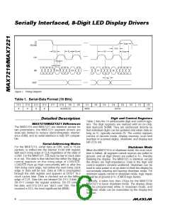
D0 D1 D2 D3 D4 D5 D6 D7 D8 D9 D10 D11 D12 D13 D14 D15
DIN
DOUT
CLK
(LSB)
(MSB)
( ) MAX7221 ONLY
_______________________________________________________________________________________
5

 MAXIM [ MAXIM INTEGRATED PRODUCTS ]