S e ria lly In t e rfa c e d , 8 -Dig it LED Dis p la y Drive rs
9/MAX721
In it ia l P o w e r-Up
On initial power-up, all control registers are reset, the
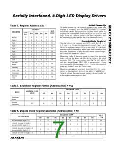
Table 2. Register Address Map
display is blanked, and the MAX7219/MAX7221 enter
shutdown mode. Program the display driver prior to
display use. Otherwise, it will initially be set to scan one
digit, it will not decode data in the data registers, and
the intensity register will be set to its minimum value.
ADDRESS
HEX
CODE
REGISTER
D15–
D12
D11 D10
D9
D8
No-Op
Digit 0
Digit 1
Digit 2
Digit 3
Digit 4
Digit 5
Digit 6
Digit 7
X
X
X
X
X
X
X
X
X
0
0
0
0
0
0
0
0
1
0
0
0
0
1
1
1
1
0
0
0
1
1
0
0
1
1
0
0
1
0
1
0
1
0
1
0
X0
X1
X2
X3
X4
X5
X6
X7
X8
De c o d e -Mo d e Re g is t e r
The decode-mode register sets BCD code B (0-9, E, H,
L, P, and -) or no-decode operation for each digit. Each
bit in the register corresponds to one digit. A logic high
selects code B decoding while logic low bypasses the
decoder. Examples of the decode mode control-regis-
ter format are shown in Table 4.
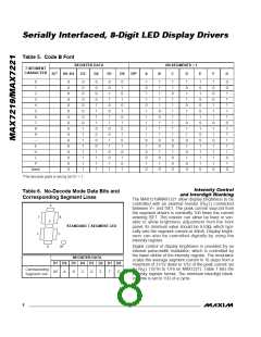
When the code B decode mode is used, the decoder
looks only at the lower nibble of the data in the digit
registers (D3–D0), disregarding bits D4–D6. D7, which
sets the decimal point (SEG DP), is independent of the
decoder and is positive logic (D7 = 1 turns the decimal
point on). Table 5 lists the code B font.
Decode
Mode
X
1
0
0
1
X9
Intensity
X
X
X
1
1
1
0
0
1
1
1
0
0
1
0
XA
XB
XC
When no-decode is selected, data bits D7–D0 corre-
spond to the segment lines of the MAX7219/MAX7221.
Table 6 shows the one-to-one pairing of each data bit
to the appropriate segment line.
Scan Limit
Shutdown
Display
Test
X
1
1
1
1
XF
Table 3. Shutdown Register Format (Address (Hex) = XC)
REGISTER DATA
ADDRESS CODE
(HEX)
MODE
D7
X
D6
X
D5
X
D4
X
D3
X
D2
X
D1
X
D0
0
Shutdown
Mode
XC
XC
Normal
Operation
X
X
X
X
X
X
X
1
Table 4. Decode-Mode Register Examples (Address (Hex) = X9)
REGISTER DATA
DECODE MODE
HEX
CODE
D7
D6
D5
D4
D3
D2
D1
D0
No decode for digits 7–0
0
0
0
0
0
0
0
0
00
01
Code B decode for digit 0
No decode for digits 7–1
0
0
0
0
0
0
0
1
Code B decode for digits 3–0
No decode for digits 7–4
0
1
0
1
0
1
0
1
1
1
1
1
1
1
1
1
0F
FF
Code B decode for digits 7–0
_______________________________________________________________________________________
7

 MAXIM [ MAXIM INTEGRATED PRODUCTS ]