Low-Cost, +5V, Serial-Input,
Voltage-Output, 16-Bit DAC
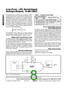
(R > 60kΩ) without degradation of INL or DNL; only
L
Applications Information
the gain error is increased by externally loading the
DAC output.
Reference and Analog Ground Inputs
The MAX5541 operates with external voltage references
from 2V to 3V, and maintains 16-bit performance with
proper reference selection and application. Ideally, the
reference’s temperature coefficient should be less than
0.4ppm/°C to maintain 16-bit accuracy to within 1LSB
over the commercial (0°C to +70°C) temperature range.
Since this converter is designed as an inverted R-2R
voltage-mode DAC, the input resistance seen by the
voltage reference is code dependent. The worst-case
input-resistance variation is from 11.5kΩ (at code 8555
hex) to 200kΩ (at code 0000 hex). The maximum
change in load current for a 2.5V reference is 2.5V/
11.5kΩ = 217µA; therefore, the required load regulation
is 7ppm/mA for a maximum error of 0.1LSB. This implies
a reference output impedance of <18mΩ. In addition,
the impedance of the signal path from the voltage refer-
ence to the reference input must be kept low because it
contributes directly to the load-regulation error.
External Output Buffer Amplifier
In unipolar mode, the output amplifier is used in a volt-
age-follower connection. The DAC’s output resistance
is constant and is independent of input code; however,
the output amplifier’s input impedance should still be as
high as possible to minimize gain errors. The DAC’s
output capacitance is also independent of input code,
thus simplifying stability requirements on the external
amplifier.
In single-supply applications, precision amplifiers with
input common-mode ranges including AGND are avail-
able; however, their output swings do not normally
include the negative rail (AGND) without significant per-
formance degradation. A single-supply op amp, such
as the MAX495, is suitable if the application does not
use codes near zero.
Since the LSBs for a 16-bit DAC are extremely small
The requirement for a low-impedance voltage reference
is met with capacitor bypassing at the reference inputs
and ground. A 0.1µF ceramic capacitor with short leads
between REF and AGND provides high-frequency
bypassing. A surface-mount ceramic chip capacitor is
preferred because it has the lowest inductance. An
additional 10µF between REF and AGND provides low-
frequency bypassing. A low-ESR tantalum, film, or
organic semiconductor capacitor works well. Leaded
capacitors are acceptable because impedance is not
as critical at lower frequencies. The circuit can benefit
from even larger bypassing capacitors, depending on
the stability of the external reference with capacitive
loading. If separate force and sense lines are not used,
connect the appropriate force and sense pins together
close to the package.
(38.15µV for V
= 2.5V), pay close attention to the
REF
external amplifier’s input specification. The input offset
voltage can degrade the zero-scale error and might
require an output offset trim to maintain full accuracy if
the offset voltage is greater than 1/2LSB. Similarly, the
input bias current multiplied by the DAC output resis-
tance (typically 6.25kΩ) contributes to the zero-scale
error. Temperature effects also must be taken into con-
sideration. Over the commercial temperature range, the
offset voltage temperature coefficient (referenced to
+25°C) must be less than 0.42µV/°C to add less than
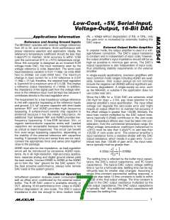
1/2LSB of zero-scale error. The external amplifier’s
input resistance forms a resistive divider with the DAC
output resistance, which results in a gain error. To con-
tribute less than 1/2LSB of gain error, the input resis-
tance typically must be greater than:
AGND must also be low impedance, as load-regulation
errors will be introduced by excessive AGND resis-
tance. As in all high-resolution, high-accuracy applica-
tions, separate analog and digital ground planes yield
the best results. Connect DGND to AGND at the AGND
pin to form the “star” ground for the DAC system. For
the best possible performance, always refer remote
DAC loads to this system ground.
1
1
6.25kΩ /
= 205MΩ
14
2
2
The settling time is affected by the buffer input capaci-
tance, the DAC’s output capacitance, and PC board
capacitance. The typical DAC output voltage settling
time is 1µs for a full-scale step. Settling time can be sig-
nificantly less for smaller step changes. Assuming a
single time-constant exponential settling response, a
full-scale step takes 12 time constants to settle to within
1/2LSB of the final output voltage. The time constant is
equal to the DAC output resistance multiplied by the
total output capacitance. The DAC output capacitance
is typically 10pF. Any additional output capacitance will
increase the settling time.
Unbuffered Operation
Unbuffered operation reduces power consumption as
well as offset error contributed by the external output
buffer. The R-2R DAC output is available directly at
OUT, allowing 16-bit performance from +V
to AGND
REF
without degradation at zero-scale. The DAC’s output
impedance is also low enough to drive medium loads
_______________________________________________________________________________________
7

 MAXIM [ MAXIM INTEGRATED PRODUCTS ]