2 -Wire S e ria l 8 -Bit DACs w it h
Ra il-t o -Ra il Ou t p u t s
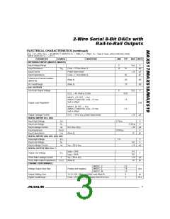
ELECTRICAL CHARACTERISTICS (continued)
(V = 5V ±10%, V
= 4V (MAX517, MAX519), R = 10kΩ, C = 100pF, T = T
to T , unless otherwise noted.
MAX
DD
REF_
L
L
A
MIN
Typical values are T = +25°C.)
A
PARAMETER
SYMBOL
CONDITIONS
MIN
TYP
MAX UNITS
Digital-Analog Glitch Impulse
Code 128 to 127
12
nV-s
Signal to Noise + Distortion
Ratio (MAX517, MAX519)
V
= 4Vp-p at 1kHz, V = 5V,
REF_ DD
SINAD
87
dB
Code = FF hex
Multiplying Bandwidth
(MAX517, MAX519)
V
REF_
= 4Vp-p, 3dB bandwidth
1
MHz
Wideband Amplifier Noise
POWER REQUIREMENTS
Supply Voltage
60
µV
RMS
V
4.5
5.5
3.0
3.5
5
V
DD
MAX517C
1.5
1.5
2.5
2.5
4
Normal mode, output(s)
unloaded, all digital inputs
MAX517E/M
mA
µA
Supply Current
I
DD
MAX518C, MAX519C
at 0V or V
DD
MAX518E/M, MAX519E/M
6
Power-down mode
20
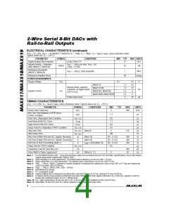
TIMING CHARACTERISTICS
(V = 5V ±10%, T = T
to T
, unless otherwise noted. Typical values are T = +25°C.)
DD
A
MIN
MAX
A
PARAMETER
SYMBOL
CONDITIONS
MIN
TYP
MAX
400
UNITS
Serial Clock Frequency
f
0
kHz
SCL
78/MAX519
Bus Free Time Between a STOP and a
START Condition
t
1.3
µs
BUF
Hold Time, (Repeated) Start Condition
Low Period of the SCL Clock
t
t
0.6
1.3
0.6
0.6
0
µs
µs
µs
µs
µs
ns
ns
ns
ns
µs
pF
ns
HD, STA
t
LOW
High Period of the SCL Clock
t
HIGH
Setup Time for a Repeated START Condition
Data Hold Time
SU, STA
HD, DAT
t
(Note 9)
0.9
Data Setup Time
t
100
SU, DAT
Rise Time of Both SDA and SCL Signals, Receiving
Fall Time of Both SDA and SCL Signals, Receiving
Fall Time of SDA Transmitting (Note 7)
Setup Time for STOP Condition
t
(Note 10)
(Note 10)
20 + 0.1Cb
20 + 0.1Cb
20 + 0.1Cb
0.6
300
300
250
R
t
t
F
F
I
≤ 6mA (Note 10)
SINK
t
SU, STO
Cb
Capacitive Load for Each Bus Line
Pulse Width of Spike Suppressed
400
50
t
SP
(Notes 6, 11)
0
Note 1: For the MAX518 (full-scale = V ) the last three codes are excluded from the TUE and DNL specifications, due to the limited
DD
output swing when loaded with 10kΩ to GND.
Note 2: Input resistance is code dependent. The lowest input resistance occurs at code = 55 hex.
Note 3: Input capacitance is code dependent. The highest input capacitance occurs at code FF hex.
Note 4:
V
= 4Vp-p, 10kHz. Channel-to-channel isolation is measured by setting the code of one DAC to FF hex and setting the
REF_
code of all other DACs to 00 hex.
= 4Vp-p, 10kHz, DAC code = 00 hex.
Note 5:
V
REF_
Note 6: Guaranteed by design.
Note 7: I2C compatible mode.
Note 8: Output settling time is measured by taking the code from 00 hex to FF hex, and from FF hex to 00 hex.
Note 9: A master device must provide a hold time of at least 300ns for the SDA signal (referred to V of the SCL signal) in order to
IL
bridge the undefined region of SCL’s falling edge.
Note 10: Cb = total capacitance of one bus line in pF. t and t measured between 0.3V and 0.7V
.
R
F
DD DD
Note 11: Input filters on the SDA and SCL inputs suppress noise spikes less than 50ns.
4
_______________________________________________________________________________________

 MAXIM [ MAXIM INTEGRATED PRODUCTS ]