Lo w -P o w e r, Du a l, 1 2 -Bit Vo lt a g e -Ou t p u t DACs
w it h S e ria l In t e rfa c e
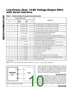
Table 1. Serial-Interface Programming Commands
16-BIT SERIAL WORD
FUNCTION
D11.......................D0
A0 C1
C0
S0
(MSB)
(LSB)
0
1
0
1
0
0
1
1
1
1
0
0
12-bit DAC data
12-bit DAC data
12-bit DAC data
12-bit DAC data
0
0
0
0
Load input register A; DAC registers are unchanged.
Load input register B; DAC registers are unchanged.
Load input register A; all DAC registers are updated.
Load input register B; all DAC registers are updated.
Load all DAC registers from the shift register
(start up both DACs with new data.).
0
1
1
12-bit DAC data
0
Update both DAC registers from their respective input registers
(start up both DACs with data previously stored in the input registers).
1
1
0
0
1
0
0
1
0
xxxxxxxxxxxx
xxxxxxxxxxxx
0
0
0
Shut down both DACs (provided PDL = 1).
4/MAX15
Update DAC register A from input register A
(start up DAC A with data previously stored in input register A).
0 0 1 x xxxxxxxx
Update DAC register B from input register B
(start up DAC B with data previously stored in input register B).
0
0
0
1 0 1 x xxxxxxxx
0
0
0
0
0
0
0
0
0
0
0
0
0
0
0
0
0
0
0
0
0
0
1 1 0 x xxxxxxxx
1 1 1 x xxxxxxxx
0 1 0 x xxxxxxxx
0 1 1 x xxxxxxxx
1 0 0 1 xxxxxxxx
1 0 0 0 xxxxxxxx
0 0 0 x xxxxxxxx
0
0
0
0
0
0
0
Shut down DAC A (provided PDL = 1).
Shut down DAC B (provided PDL = 1).
UPO goes low (default).
UPO goes high.
Mode 1, DOUT clocked out on SCLK’s rising edge.
Mode 0, DOUT clocked out on SCLK’s falling edge (default).
No operation (NOP).
x = Don’t care
Note: D11, D10, D9, and D8 become control bits when A0, C1, and C0 = 0. S0 is a sub bit, always zero.
saved, allowing the MAX5154/MAX5155 to recall the
output state prior to entering shutdown when returning
to normal mode. Exit shutdown by recalling the previ-
ous condition or by updating the DAC with new infor-
mation. When returning to normal operation (exiting
shutdown), wait 20µs for output stabilization.
SCLK
SK
MICROWIRE
PORT
MAX5154
MAX5155
DIN
CS
SO
I/O
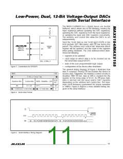
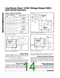
S e ria l In t e rfa c e
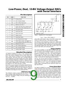
The MAX5154/MAX5155 3-wire serial interface is com-
patible with both Microwire (Figure 2) and SPI/QSPI
(Figure 3) serial-interface standards. The 16-bit serial
input word consists of an address bit, two control bits,
12 bits of data (MSB to LSB), and one sub bit as shown
in Figure 4. The address and control bits determine the
MAX5154/ MAX5155’s response, as outlined in Table 1.
Figure 2. Connections for Microwire
10 ______________________________________________________________________________________

 MAXIM [ MAXIM INTEGRATED PRODUCTS ]