P re c is io n , Hig h -S id e
Cu rre n t -S e n s e Am p lifie rs
______________________________________________________________P in De s c rip t io n
PIN
NAME
FUNCTION
MAX471
MAX472
Shutdown. Connect to ground for normal operation. When high, supply current is
less than 5µA.
1
1
SHDN
RS+
Battery (or power) side of the internal current-sense resistor. The “+” indicates direction of
flow for SIGN output only. Connect pins 2 and 3 together at the package.
2, 3
—
—
—
4
2
3
4
N.C.
RG1
GND
No Connect—no internal connection
Gain Resistor. Connect to battery side of current-sense resistor through the gain resistor.
Ground or Battery Negative Terminal
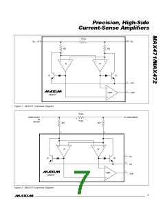
An open-collector logic output. For the MAX471, a low level indicates current is flowing from
5
5
SIGN
RS- to RS+. For the MAX472, a low level indicates a negative V
(see Figure 2). SIGN is
SENSE
1/MAX472
high impedance when SHDN is high. Leave open if SIGN is not needed.
Load side of the internal current-sense resistor. The “-” indicates direction of flow for SIGN
output only. Connect pins 6 and 7 together at the package.
6, 7
—
RS-
—
—
6
7
RG2
Gain Resistor. Connect to load side of current-sense resistor through the gain resistor.
V
CC
Power input for MAX472. Connect to sense resistor (R ) junction with RG1.
SENSE
Current output that is proportional to the magnitude of the sensed current flowing through
R . A 2kΩ resistor from this pin to ground will result in a voltage equal to 1V/Amp of
SENSE
8
8
OUT
sensed current in the MAX471.
I
= (I
x R
) / RG1
SENSE
OUT
LOAD
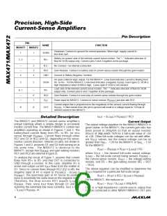
_______________De t a ile d De s c rip t io n
The MAX471 and MAX472 current-sense amplifier’s
unique topology allows a simple design to accurately
monitor current flow. The MAX471/MAX472 contain two
amplifiers operating as shown in Figures 1 and 2. The
battery/load current flows from RS+ to RS- (or vice
Cu rre n t Ou t p u t
The output voltage equation for the MAX471/MAX472 is
given below. In the MAX471, the current-gain ratio has
b e e n p re s e t to 500µA/A s o tha t a n outp ut re s is tor
) of 2kΩ yields 1V/A for a full-scale value of +3V
at ±3A. Other full-scale voltages can be set with differ-
ent R values, but the output voltage can be no
(R
OUT
versa) through R
. Current flows through either
SENSE
RG1 and Q1 or RG2 and Q2, depending on the sense-
resistor current direction. Internal circuitry, not shown in
Figures 1 and 2, prevents Q1 and Q2 from turning on at
the s a me time . The MAX472 is id e ntic a l to the
OUT
greater than V
for the MAX472.
- 1.5V for the MAX471 or V
- 1.5V
RG_
RS+
V
= (R
x R
x I
) / RG
OUT
SENSE
OUT LOAD
MAX471, except that R
and gain-setting resistors
SENSE
where V
= the desired full-scale output voltage,
OUT
RG1 and RG2 are external (Figure 2).
I
= the full-scale current being sensed, R
=
LOAD
SENSE
To analyze the circuit of Figure 1, assume that current
flows from RS+ to RS- and that OUT is connected to
GND through a resistor. In this case, amplifier A1 is
the current-sense resistor, R
= the voltage-setting
resistor, and RG = the gain-setting resistor (RG = RG1
= RG2).
OUT
active and output current I
flows from the emitter of
OUT
The above equation can be modified to determine the
Q1. Since no current flows through RG2 (Q2 is off), the
negative input of A1 is equal to V - (I
R
required for a particular full-scale range:
OUT
x
LOAD
SOURCE
R
). The open-loop gain of A1 forces its positive
SENSE
R
= (V
x RG) / (I
x R
)
SENSE
OUT
OUT
LOAD
input to essentially the same level as the negative input.
The re fore , the d rop a c ros s RG1 e q ua ls I
R
For the MAX471, this reduces to:
= V / (I
x
LOAD
R
x 500µA/A)
LOAD
OUT
OUT
. Then, since I
flows through Q1 and RG
SENSE
OUT
(ignoring the extremely low base currents), I
x RG1
OUT
OUT is a high-impedance current-source output that
can be connected to other MAX471/MAX472 OUT pins
= I
x R
, or:
SENSE
LOAD
6
_______________________________________________________________________________________

 MAXIM [ MAXIM INTEGRATED PRODUCTS ]