P re c is io n , Hig h -S id e
Cu rre n t -S e n s e Am p lifie rs
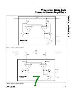
1/MAX472
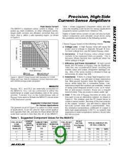
Peak Sense Current
The MAX471’s maximum sense current is 3ARMS. For
power-up, fault conditions, or other infrequent events,
larger peak currents are allowed, provided they are
short—that is, within a safe operating region, as shown
in Figure 5.
Table 1 shows suggested component values and indi-
cates the resulting scale factors for various applications
required to sense currents from 100mA to 10A.
Higher or lower sense-current circuits can also be built.
Select components and calculate circuit errors using
the guidelines and formulas in the following section.
50
R
SENSE
Small
Outline
fuse
DIP
45
Choose R
based on the following criteria:
SENSE
fuse
time
T = +25°C
A
40
35
30
25
20
15
10
5
a) Voltage Loss: A high R
value will cause the
power-source voltage to degrade through IR loss.
SENSE
time
For least voltage loss, use the lowest R value.
SENSE
b) Accuracy: A hig h R
va lue a llows lowe r
SENSE
currents to be measured more accurately. This is
because offsets become less significant when the
sense voltage is larger.
c) Efficiency and Power Dissipation: At high current
levels, the I2R losses in R
may be significant.
SENSE
0
Ta ke this into c ons id e ra tion whe n c hoos ing the
resistor value and power dissipation (wattage) rat-
ing. Also, if the sense resistor is allowed to heat up
excessively, its value may drift.
10µ
100µ
PULSE WIDTH (sec)
DIP safe
Small Outline safe
1m
10m
operating region
operating region
d) Inductance: If there is a large high-frequency com-
Figure 5. MAX471 Pulse Current Safe Operation for 10,000
Pulses and Fuse Time for Continuous Current. Pulse tests done
with 250mW average power dissipation.
ponent to I , you will want to keep inductance
SENSE
low. Wire-wound resistors have the highest induc-
tance, while metal film is somewhat better. Low-
inductance metal-film resistors are available. Instead
of being spiral wrapped around a core, as in metal-
film or wire-wound resistors, these are a straight
band of metal. They are made in values under 1Ω.
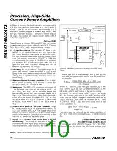
MAX4 7 2
R
, RG1, and RG2 are externally connected on
SENSE
the MAX472. V
c a n b e c onne c te d to e ithe r the
CC
load/charge or power-source/battery side of the sense
re s is tor. Conne c t V to the loa d /c ha rg e s id e of
e) Cost: If the cost of R
becomes an issue, you
SENSE
CC
may want to use an alternative solution, as shown in
Figure 6. This solution uses the PC board traces to
create a sense resistor. Because of the inaccuracies
of the copper “resistor,” you will need to adjust the
full-scale current value with a potentiometer. Also,
the resistance temperature coefficient of copper is
fairly high (approximately 0.4%/°C), so systems that
experience a wide temperature variance should take
this into account.
R
if you want to include the MAX472 current drain
SENSE
in the measured current.
Suggested Component Values
for Various Applications
The general circuit of Figure 4 is useful in a wide variety
of applications. It can be used for high-current applica-
tions (greater than 3A), and also for those where the full-
scale load current is less than the 3A of the MAX471.
Table 1. Suggested Component Values for the MAX472
CURRENT-
SENSE
RESISTOR,
SCALE
FACTOR,
FULL-SCALE
LOAD
CURRENT,
GAIN-SETTING
RESISTORS,
RG1 = RG2
(Ω)
OUTPUT
RESISTOR,
FULL-SCALE
OUTPUT
VOLTAGE,
TYPICAL ERROR AT X%
OF FULL LOAD (%)
V
/I
OUT SENSE
R
OUT
R
(V/A)
SENSE
I
(A)
(kΩ)
V
OUT
(V)
SENSE
1%
14
14
13
12
10%
2.5
100%
0.9
(mΩ)
500
50
0.1
1
200
200
100
50
10
10
5
2.5
2.5
2.5
2
25
2.5
0.5
0.2
2.5
0.9
5
10
2.0
1.1
10
5
2
2.0
1.6
_______________________________________________________________________________________
9

 MAXIM [ MAXIM INTEGRATED PRODUCTS ]