P re c is io n , Hig h -S id e
Cu rre n t -S e n s e Am p lifie rs
ABSOLUTE MAXIMUM RATINGS
Supply Voltage, RS+, RS-, V to GND....................-0.3V, +40V
CC
Continuous Power Dissipation (T = +70°C)
A
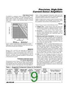
RMS Current, RS+ to RS- (MAX471 only)..........................±3.3A
Peak Current, (RS+ to RS-) ......................................see Figure 5
Differential Input Voltage, RG1 to RG2 (MAX472 only) .....±0.3V
Voltage at Any Pin Except SIGN
MAX471 (Note 1):
Plastic DIP (derate 17.5mW/°C above +70°C) ..................1.4W
SO (derate 9.9mW/°C above +70°C).............................791mW
MAX472 :
MAX471 only ...........................................-0.3V to (RS+ - 0.3V)
Plastic DIP (derate 9.09mW/°C above +70°C) ..............727mW
SO (derate 5.88mW/°C above +70°C)...........................471mW
Operating Temperature Ranges
MAX472 only ..........................................-0.3V to (V + 0.3V)
CC
Voltage at SIGN......................................................-0.3V to +40V
Current into SHDN, GND, OUT, RG1, RG2, V ................±50mA
Current into SIGN.................................................+10mA, -50mA
MAX47_C_A........................................................0°C to +70°C
MAX47_E_A .....................................................-40°C to +85°C
Junction Temperature Range ............................-60°C to +150°C
Storage Temperature Range .............................-60°C to +160°C
Lead Temperature (soldering, 10sec) .............................+300°C
CC
Note 1: Due to special packaging considerations, MAX471 (DIP, SO) has a higher power dissipation rating than the MAX472. RS+
and RS- must be soldered to large copper traces to achieve this dissipation rating.
1/MAX472
Stresses beyond those listed under “Absolute Maximum Ratings” may cause permanent damage to the device. These are stress ratings only, and functional
operation of the device at these or any other conditions beyond those indicated in the operational sections of the specifications is not implied. Exposure to
absolute maximum rating conditions for extended periods may affect device reliability.
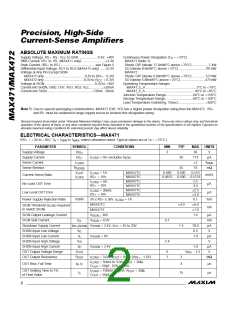
ELECTRICAL CHARACTERISTICS—MAX471
(RS+ = +3V to +36V, T = T
A
to T
, unless otherwise noted. Typical values are at T = +25°C.)
A
MAX
MIN
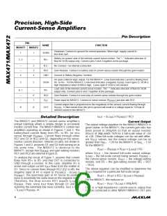
PARAMETER
Supply Voltage
SYMBOL
CONDITIONS
MIN
TYP
MAX
36
UNITS
V
V
RS+
3
Supply Current
Sense Current
I
I
= 0A, excludes I
SIGN
50
113
±3
µA
RS+
LOAD
I
A
RMS
LOAD
Sense Resistor
R
35
70
0.510
0.5125
2.5
mΩ
SENSE
MAX471C
0.490
0.4875
0.500
0.500
I
/
I
= 1A,
OUT
LOAD
Current-Sense Ratio
No-Load OUT Error
Low-Level OUT Error
mA/A
I
RS+ = 10V
MAX471E
MAX471C
MAX471E
MAX471C
MAX471E
= 1A
LOAD
I
= 0A,
LOAD
µA
RS+ = 10V
3.0
±2.5
±3.0
0.1
I
= 30mA,
LOAD
µA
RS+ = 10V
3V ≤ RS+ ≤ 36V, I
MAX471C
Power-Supply Rejection Ratio
PSRR
%/V
LOAD
±4.0
1.5
±6.0
±7.0
1.0
SIGN Threshold (I
to switch SIGN)
required
LOAD
mA
MAX471E
SIGN Output Leakage Current
SIGN Sink Current
V
36V
µA
mA
µA
V
SIGN =
I
OL
V
= 0.3V
0.1
2.4
SIGN
Shutdown Supply Current
SHDN Input Low Voltage
SHDN Input Low Current
SHDN Input High Voltage
SHDN Input High Current
OUT Output Voltage Range
OUT Output Resistance
I
V
= 2.4V; V = 3V to 20V
CC
18.0
0.3
RS+(SHDN)
SHDN
V
IL
I
IL
V
= 0V
1.0
µA
V
SHDN
V
IH
I
IH
V
= 2.4V
1.0
µA
V
SHDN
V
0
1
V
- 1.5
OUT
OUT
RS+
R
I
= 3.0A, V
= 0V to (V - 1.5V)
RS+
3
4
MΩ
LOAD
OUT
I
= 50mA to 3.0A, R
= 2kΩ,
LOAD
OUT
OUT Rise, Fall Time
t , t
µs
µs
R
F
C
= 50pF, 10% to 90%
OUT
OUT Settling Time to 1%
of Final Value
I
= 100mA to 3.0A, R = 2kΩ,
OUT
LOAD
t
s
15
C
= 50pF
OUT
2
_______________________________________________________________________________________

 MAXIM [ MAXIM INTEGRATED PRODUCTS ]