MAX1978 Evaluation Kit
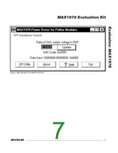
The program starts with ratio = 0.5. This sets the DAC
The utility handles the data only in byte (8-bit) format.
Data longer than a byte must be handled as multiple
bytes. For example, a 16-bit word must be broken into
two 8-bit bytes. To write data to the slave device, enter
the data into the field labeled “Data bytes to be written:”
Each data byte should be hexadecimal, prefixed by 0x,
and separated with a comma. Press the Send Now
button to write the data to the slave.
output to 0.75V, which corresponds to +25°C.
A ratio of 0.67 sets the DAC output to 1V, which corre-
sponds to approximately +10°C. A ratio of 0.33 sets the
DAC output to 0.5V, or approximately +40°C. The slope
is approximately -14mV/°C for a typical NTC.
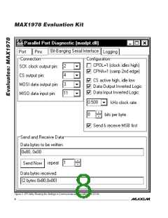
General-Purpose SPI Utility
There are two methods for communicating with the
MAX5144 DAC: through the user-interface panel or
through the general-purpose SPI utility. This utility
(Figure 3) configures SPI parameters such as clock
polarity (CPOL), clock phase (CPHA), and chip-select
(CS) polarity. The fields where pin numbers are
required apply to the pins of the parallel port connector.
To read data from the slave device, the field “Data
bytes to be written:” must contain hexadecimal values.
Include the same number of bytes as to be read from
the slave.
Note: The MAX5144 is a write-only device and cannot
be read.
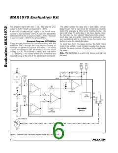
INTO
CTLI
1.5V
REF
JU2
SET POINT
DAC
DIFOUT
INT-
1.5V
REF
FB+
JU4
50R
1.5V
REF
INTEGRATOR
OS2
OS1
TEC+
R
20kΩ
PWM
SECTION
THERM
R
TEC-
N
P
1.5V
REF
FB-
50R
10kΩ
MAX1978
CHOPPER AMP
10kΩ THERMISTOR
Figure 1. Thermal-Loop Functional Diagram for the MAX1978 EV Kit
6
_______________________________________________________________________________________

 MAXIM [ MAXIM INTEGRATED PRODUCTS ]