MAX1978 Evaluation Kit
THERM voltage moves away from 0.75V toward either
0V or 1.5V. If this occurs, shut down the MAX1978 and
reverse TEC+ and TEC- connections.
Procedure
The MAX1978 EV kit is a fully assembled and tested
surface-mount board. Follow the steps below to verify
board operation. Do not turn on the power supply
until all connections are completed:
14) Once proper operation is verified, other tempera-
tures can be set with R24, the DAC, or an external
voltage applied to SET_POINT. (1V is approximately
+10°C; 0.5V is approximately +40°C. The slope is
approximately -14mV/°C for a typical NTC.)
1) Place a shunt across pins 2-3 on JU1 to set the
frequency to 500kHz.
2) Place a shunt across JU2 to connect the thermal
loop to CTLI.
Detailed Description
3) Place a shunt across pins 2-3 on JU4 to select the
potentiometer.
Voltage and Current-Limit Settings
The MAX1978 provides control of the maximum differ-
ential TEC voltage and the maximum positive and neg-
ative TEC currents.
4) Place a shunt across pins 2-3 on JU3 to disable the
MAX1978 output.
5) Obtain TEC module specifications for absolute
maximum TEC voltage, absolute maximum cooling
current, and absolute maximum heating current. Set
these (or lower) limits at the MAX1978’s MAXV,
MAXIP (heating current), MAXIN (cooling current)
inputs. See Tables 1, 2, and 3 to select resistors, or
refer to the MAX1978 data sheet.
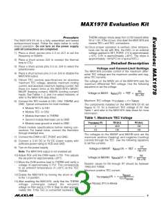
The voltage on the MAXV pin of the MAX1978 sets the
maximum differential TEC voltage. Use the following
equations to set the voltage:
R3
Voltage on MAXV: V
(V) = REF ×
MAXV
R2 + R3
Maximum TEC voltage: V
= 4 ✕ V
MAXV
TEC(MAX)
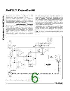
6) Connect the TEC module to OS1, OS2, THERM, and
GND. Typical connections for most modules:
The components installed on the MAX1978 EV kit set
to 1V, for a maximum TEC voltage of 4V. See
V
MAXV
• Module TEC+ to OS1
Table 1 and refer to the MAX1978 data sheet for more
information.
• Module TEC- to OS2
• Module thermistor to THERM
• Second module thermistor pin to GND
• Module case ground or shield to GND
Table 1. Maximum TEC Voltage
V
(V)
R2 (kΩ)
49.9
R3 (kΩ)
100
TEC(MAX)
4
Check module specifications before making con-
nections. For lowest noise, connect the thermistor
through shielded wire.
2.6
130
100
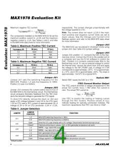
The voltages on the MAXIP and MAXIN pins set the
maximum positive (heating) and negative (cooling)
currents through the TEC. Use the following equations
to set the currents:
7) Connect the DVM to SET_POINT and GND.
8) Connect a 3.3V DC or 5V DC power supply with
sufficient power rating to VDD and GND.
R7
R6 + R7
9) Turn on the power supply.
Voltage on MAXIP: V
(V) = REF ×
MAXIP
Note: The MAX1978 output is not enabled yet.
10) Adjust R24 until the DVM reads 0.75V. This adjusts
R5
R4 + R5
Voltage on MAXIN: V
(V) = REF ×
MAXIN
the set point for approximately +25°C.
11) Move the DVM positive lead to THERM and verify a
voltage of approximately 0.75V. This corresponds
to an ambient temperature of +25°C at the TEC
module.
Resistor values for R2 through R7 should be between
10kΩ and 100kΩ.
Maximum positive TEC current:
12) Enable the MAX1978 by moving the shunt on JU3
to the 1-2 position.
V
MAXIP
I
(A) = +
TECP(MAX)
10 × R
SENSE
13) After enabling the MAX1978, verify that the THERM
voltage converges toward the set-point
voltage on R24 (set to 0.75V in Step 9) after approxi-
mately 30s. If the TEC is connected backward, the
where R
(R1) is 68mΩ.
SENSE
_______________________________________________________________________________________
3

 MAXIM [ MAXIM INTEGRATED PRODUCTS ]