MAX1978 Evaluation Kit
Maximum negative TEC current:
respectively. The current changes proportionally with
the voltage applied to CTLI.
V
MAXIN
I
(A) = −
TECN(MAX)
10 × R
Note: The current does not reach 2.2A if the maxi-
mum positive and negative current limits are set to
lower values. See the Voltage and Current-Limit
Settings section and refer to the MAX1978 data sheet
for more information.
SENSE
The components installed on the MAX1978 EV kit set the
maximum positive current to +2.2A and the maximum
negative current to -2.2A. See Tables 2 and 3, and refer
to the MAX1978 data sheet for more information.
Jumper JU3
The MAX1978 can be placed in shutdown mode using
jumper JU3. See Table 4 for jumper settings.
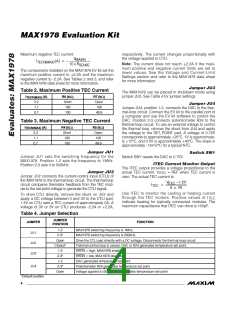
Table 2. Maximum Positive TEC Current
I
(A)
R6 (kΩ)
Short
100
R7 (kΩ)
Open
100
TECP(MAX)
2.2
1.1
0.7
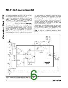
Jumper JU4
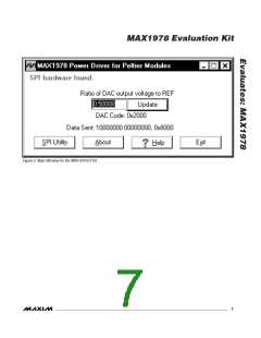
Jumper JU4, position 1-2, connects the DAC to the ther-
mal-loop circuit. Connect the EV kit to the parallel port of
a computer and use the EV kit software to control the
DAC. Position 2-3 connects potentiometer R24 to the
thermal-loop circuit. To use an external voltage to control
the thermal loop, remove the shunt from JU4 and apply
the voltage to the SET_POINT pad. A voltage of 0.75V
corresponds to approximately +25°C. 1V is approximate-
ly +10°C, and 0.5V is approximately +40°C. The slope is
approximately -14mV/°C for a typical NTC.
100
49.9
Table 3. Maximum Negative TEC Current
I
(A)
R4 (kΩ)
Short
100
R5 (kΩ)
Open
100
TECN(MAX)
2.2
1.1
0.7
100
49.9
Jumper JU1
Switch SW1
Jumper JU1 sets the switching frequency for the
MAX1978. Position 1-2 sets the frequency to 1MHz.
Position 2-3 sets it to 500kHz.
Switch SW1 resets the DAC to 0.75V.
ITEC Current Monitor Output
The ITEC output provides a voltage proportional to the
Jumper JU2
Jumper JU2 connects the current-control input (CTLI) of
the MAX1978 to the thermal-loop circuit. The thermal-loop
circuit compares thermistor feedback from the TEC mod-
ule to the set-point voltage to generate the CTLI signal.
actual TEC current. V
= REF when TEC current is
ITEC
zero. The actual TEC current is:
V
−1.5V
ITEC
I
=
TEC
8 × R1
Use ITEC to monitor the cooling or heating current
through the TEC module. Positive values of I
To drive CTLI directly, remove the shunt on JU2 and
apply a DC voltage between 0 and 3V to the CTLI pad;
1.5V on CTLI sets a TEC current of approximately 0A. A
voltage of 0V or 3V on CTLI produces -2.2A or +2.2A,
TEC
indicate heating for typically connected modules. The
maximum capacitance that ITEC can drive is 100pF.
Table 4. Jumper Selection
JUMPER
POSITION
JUMPER
FUNCTION
1-2
2-3*
MAX1978 switching frequency is 1MHz.
MAX1978 switching frequency is 500kHz.
JU1
JU2
JU3
Open
Closed*
1-2
Drive the CTLI pad directly with a DC voltage. Disconnects the thermal-loop circuit.
Thermal-control loop is closed. DAC or R24 generates temperature set point.
SHDN = high, MAX1978 enabled.
2-3*
SHDN = low, MAX1978 disabled.
1-2
DAC generates temperature set point.
JU4
2-3*
Potentiometer R24 generates temperature set point.
Voltage applied to SET_POINT generates temperature set point.
Open
*Default position
4
_______________________________________________________________________________________

 MAXIM [ MAXIM INTEGRATED PRODUCTS ]