MAX1978 Evaluation Kit
port or any other connector that is physically similar
to the 25-pin parallel printer port.
Controlling DAC Through
Parallel Port
Required Equipment
In addition to the equipment listed under the Quick
Start section, the the following equipment is required:
8) The MAX1978.EXE software program can be run
from the floppy or hard drive. Use the Windows
program manager to run the program. If desired, you
can use the INSTALL.EXE program to copy the files
and create icons for them in the Windows 95/98/2000
start menu. An uninstall program is included with the
software. Click on the UNINSTALL icon to remove
the EV kit software from the hard drive.
• A computer running Windows 95, 98, or 2000.
Note: Windows 2000 requires the installation of a dri-
ver; refer to Win2000.pdf or Win2000.txt located on
the diskette.
9) Connect a 3.3V DC or 5.0V DC power supply with
sufficient power rating to VDD and GND.
• A parallel printer port (25-pin socket on the back of
the computer)
10) Turn on the power supply.
• A standard 25-pin, straight-through, male-to-female
cable (printer extension cable) to connect the
computer’s parallel port to the MAX1978 EV kit
11) Start the MAX1978 program by opening its icon in
the start menu. At program startup, the software
forces the DAC to 0.75V, which corresponds to
approximately +25°C.
Procedure
1) Place a shunt across pins 2-3 on JU1 to set the
frequency to 500kHz.
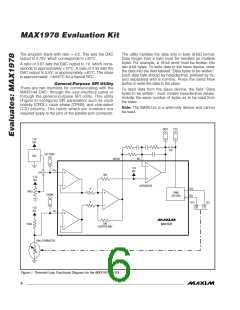
12) Connect the DVM to THERM and verify a voltage of
approximately 0.75V. This represents +25°C at the
TEC module.
2) Place a shunt across JU2 to connect the thermal
loop to CTLI.
13) Enable the MAX1978 by moving the shunt on JU3
to the 1-2 position.
3) Place a shunt across pins 1-2 on JU4 to select the
DAC.
14) After enabling the MAX1978, verify that the THERM
voltage converges toward the DAC voltage (0.75V)
after approximately 30s. If the TEC is connected
backward, the THERM voltage moves away from
0.75V toward either 0V or 1.5V. If this occurs, shut
down the MAX1978 and reverse TEC+ and TEC-
connections.
4) Place a shunt across pins 2-3 on JU3 to disable the
MAX1978 output.
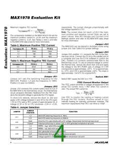
5) Obtain TEC module specifications for absolute
maximum TEC voltage, absolute maximum cooling
current, and absolute maximum heating current. Set
these (or lower) limits at the MAX1978’s MAXV,
MAXIP (heating current), MAXIN (cooling current)
inputs. See Tables 1, 2, and 3 to select resistors, or
refer to the MAX1978 data sheet.
15) Once proper operation is verified, other tempera-
tures can be set with the DAC (see the Software
User Interface section).
6) Connect the TEC module to OS1, OS2, THERM,
and GND. Typical connections for most modules:
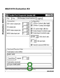
Software User Interface
The user interface is easy to operate. Use either the
mouse or the Tab key to navigate.
• Module TEC+ to OS1
• Module TEC- to OS2
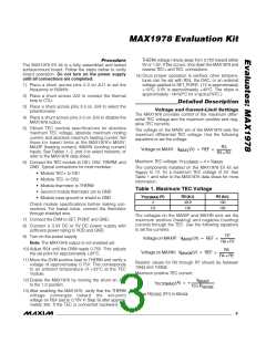
To program the DAC, enter the ratio of the desired DAC
output voltage (V
) to the reference voltage (REF):
DAC
• Module thermistor to THERM
• Second module thermistor pin to GND
• Module case ground or shield to GND
V
DAC
Ratio =
REF
Check module specifications before making con-
nections. For lowest noise, connect the thermistor
through shielded wire.
where REF = 1.5V.
The ratio must be a decimal number between zero and
1. Press Enter or click on the Update button to send the
data to the DAC.
7) Connect a cable from the computer’s parallel port
to the MAX1978 EV kit. Use a straight-through 25-
pin female-to-male cable. To avoid damaging the
EV kit or your computer, do not use a 25-pin SCSI
_______________________________________________________________________________________
5

 MAXIM [ MAXIM INTEGRATED PRODUCTS ]