MAX17047/MAX17050
ModelGauge m3 Fuel Gauge
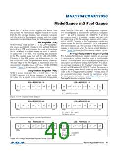
When Tex = 1 in the CONFIG register, the device does
value. See the TGAIN and TOFF configuration registers.
The resulting data is placed in the Temperature register
every 1.4s with a resolution of +0.0039NC. If an 8-bit
temperature reading is desired, the host can read only
the upper byte of the Temperature register with a resolu-
tion of +1.0NC. Contents of the Temperature register are
indeterminate for the first conversion cycle time period
after device power-up. The last value of the Temperature
register is maintained when the device enters shutdown
mode. Figure 58 shows the Temperature register format.
not update the Temperature register based on results
from the AIN pin A/D. Instead, host software must peri-
odically write the Temperature register with the known
application temperature to keep the fuel gauge accurate.
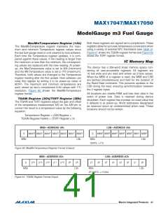
AIN Register (27h)
While in active mode and Ten = 1 in the CONFIG register,
the device periodically measures the voltage between
pins AIN and CSP and compares the result to the voltage
of the THRM pin. The device stores the result, a ratiomet-
ric value from 0 to 100%. The resulting data is placed
in the AIN register every 1.4s with an LSb of 0.0122%.
Contents of the AIN register are indeterminate for the
first conversion cycle time period after device power-up.
The last value of the AIN register is maintained when the
device enters shutdown mode or if Ten = 0 in the CONFIG
register. Figure 57 shows the AIN register format.
AverageTemperature Register (16h)
The AverageTemperature register reports an average
of temperature register readings over a configurable
6min to 12h time period. See the FilterCFG register (29h)
description for details on setting the time filter. The result-
ing average is placed in the AverageTemperature regis-
ter with an LSb value of 0.0039NC. The first Temperature
register reading after device power-up sets the starting
point of the AverageTemperature filter. The last value of
the AverageTemperature register is maintained when
the device enters shutdown mode. Figure 59 shows the
AverageTemperature register format.
Temperature Register (08h)
While in active mode and Tex = 0 and Ten = 1 in the
CONFIG register, the device converts the AIN regis-
ter value into a signed two’s-complement temperature
MSB—ADDRESS 27h
LSB—ADDRESS 27h
-1
-2
-3
-4
-5
-6
-7
-8
-9
-10
-11
-12
-13
2
2
2
2
2
2
2
2
2
2
2
2
2
X
X
X
MSb
LSb
MSb
LSb
-13
2
UNITS: 0.0122%
Figure 57. AIN Register Format (Output)
MSB—ADDRESS 08h
LSB—ADDRESS 08h
6
5
4
3
2
1
0
-1
2
-2
-3
-4
-5
-6
-7
-8
2
S
2
2
2
2
2
2
2
2
2
2
2
2
2
MSb
LSb
MSb
-8
LSb
2
UNITS: +0.0039NC
0
2 UNITS: +1.0NC
Figure 58. Temperature Register Format (Input/Output)
MSB—ADDRESS 16h
LSB—ADDRESS 16h
6
5
4
3
2
1
0
-1
-2
-3
-4
-5
-6
-7
-8
2
S
2
2
2
2
2
2
2
2
2
2
2
2
2
2
MSb
LSb
MSb
-8
LSb
2
UNITS: +0.0039NC
0
2 UNITS: +1.0NC
Figure 59. AverageTemperature Register Format (Output)
���������������������������������������������������������������� Maxim Integrated Products 40

 MAXIM [ MAXIM INTEGRATED PRODUCTS ]