MAX17047/MAX17050
ModelGauge m3 Fuel Gauge
bits. To generate an Acknowledge, the receiving device
2-Wire Bus System
must pull SDA low before the rising edge of the acknowl-
edge-related clock pulse (ninth pulse) and keep it low
until SCL returns low. To generate a No Acknowledge
(also called NACK), the receiver releases SDA before
the rising edge of the acknowledge-related clock pulse
and leaves SDA high until SCL returns low. Monitoring
the acknowledge bits allows for detection of unsuccess-
ful data transfers. An unsuccessful data transfer can
occur if a receiving device is busy or if a system fault has
occurred. In the event of an unsuccessful data transfer,
the bus master should reattempt communication.
The 2-wire bus system supports operation as a slave-
only device in a single or multislave, and single or
multimaster system. Up to 128 slave devices may share
the bus by uniquely setting the 7-bit slave address. The
2-wire interface consists of a serial data line (SDA) and
serial clock line (SCL). SDA and SCL provide bidirec-
tional communication between the IC (slave device) and
a master device at speeds up to 400kHz. The device’s
SDA pin operates bidirectionally, that is, when the device
receives data, SDA operates as an input, and when the
device returns data, SDA operates as an open-drain out-
put, with the host system providing a resistive pullup. The
device always operates as a slave device, receiving and
transmitting data under the control of a master device.
The master initiates all transactions on the bus and gen-
erates the SCL signal, as well as the START and STOP
bits, which begin and end each transaction.
Data Order
A byte of data consists of 8 bits ordered most significant
bit (MSb) first. The least significant bit (LSb) of each byte
is followed by the Acknowledge bit. Device registers
composed of multibyte values are ordered least signifi-
cant byte (LSB) first.
Slave Address
A bus master initiates communication with a slave device
by issuing a START condition followed by a Slave Address
(SAddr) and the read/write (R/W) bit. When the bus is idle,
the device continuously monitors for a START condition
followed by its slave address. When the device receives a
slave address that matches the value in its Programmable
Slave Address register, it responds with an Acknowledge
bit during the clock period following the R/W bit. The 7-bit
Programmable Slave Address register is factory pro-
grammed and cannot be changed by the user.
Bit Transfer
One data bit is transferred during each SCL clock cycle,
with the cycle defined by SCL transitioning low to high
and then high to low. The SDA logic level must remain
stable during the high period of the SCL clock pulse.
Any change in SDA when SCL is high is interpreted as a
START or STOP control signal.
Bus Idle
The bus is defined to be idle, or not busy, when no mas-
ter device has control. Both SDA and SCL remain high
when the bus is idle. The STOP condition is the proper
method to return the bus to the idle state.
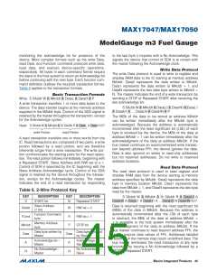
IC SLAVE ADDRESS
0110110
START and STOP Conditions
The master initiates transactions with a START condition
(S), by forcing a high-to-low transition on SDA while SCL
is high. The master terminates a transaction with a STOP
condition (P), a low-to-high transition on SDA while SCL
is high. A Repeated START condition (Sr) can be used
in place of a STOP then START sequence to terminate
one transaction and begin another without returning the
bus to the idle state. In multimaster systems, a Repeated
START allows the master to retain control of the bus. The
START and STOP conditions are the only bus activities in
which the SDA transitions when SCL is high.
Read/Write Bit
The R/W bit following the slave address determines the
data direction of subsequent bytes in the transfer. R/W
= 0 selects a write transaction, with the following bytes
being written by the master to the slave. R/W = 1 selects
a read transaction, with the following bytes being read
from the slave by the master.
Bus Timing
The device is compatible with any bus timing up to
400kHz. No special configuration is required to operate
at any speed.
2-Wire Command Protocols
The command protocols involve several transaction
formats. The simplest format consists of the master
writing the START bit, slave address, R/W bit, and then
Acknowledge Bits
Each byte of a data transfer is acknowledged with an
Acknowledge bit (A) or a No Acknowledge bit (N). Both
the master and the device slave generate acknowledge
���������������������������������������������������������������� Maxim Integrated Products 44

 MAXIM [ MAXIM INTEGRATED PRODUCTS ]