MAX17047/MAX17050
ModelGauge m3 Fuel Gauge
• Cell Capacity (FullCapNom). This is the total cell
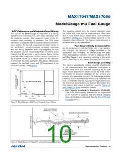
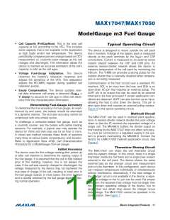
Typical Operating Circuit
capacity at full, according to the VFG. This includes
some capacity that is not available to the application
at high loads and/or low temperature. The device
periodically compares percent change based on OCV
measurement vs. coulomb-count change as the cell
charges and discharges. This information allows the
device to maintain an accurate estimation of the cell’s
capacity in mAh as the cell ages.
The device is designed to mount outside the cell pack
that it monitors. Voltage of the battery pack is measured
directly at the pack terminals by the V
and CSP
BATT
connections. Current is measured by an external sense
resistor placed between the CSP and CSN pins. An
external resistor-divider network allows the device to
measure temperature of the cell pack by monitoring the
AIN pin. The THRM pin provides a strong pullup for the
resistor-divider that is internally disabled when tempera-
ture is not being measured.
• Voltage Fuel-Gauge Adaptation. The device
observes the battery’s relaxation response and
adjusts the dynamics of the VFG. This adaptation
adjusts the RCOMP0 register during qualified cell
relaxation events.
2
Communication to the host occurs over a standard I C
interface. SCL is an input from the host, and SDA is an
open-drain I/O pin that requires an external pullup. The
ALRT pin is an output that can be used as an external
interrupt to the host processor if certain application con-
ditions are detected. ALRT can also function as an input,
allowing the host to shut down the device. This pin is
also open drain and requires an external pullup resistor.
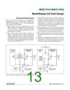
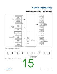
Figure 5 is the typical operating circuit.
• Empty Compensation. The device updates inter-
nal data whenever cell empty is detected (V
V�empty) to account for cell age or other cell devia-
<
CELL
tions from the characterization information.
Determining Fuel-Gauge Accuracy
To determine the true accuracy of a fuel gauge, as expe-
rienced by end users, the battery should be exercised
in a dynamic manner. The end-user accuracy cannot be
understood with only simple cycles.
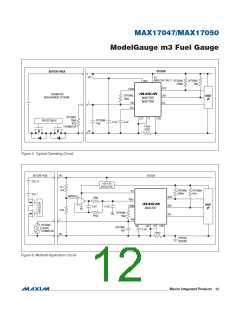
Multicell Circuit
The MAX17047 can be used in multicell pack applica-
tions. A resistor-divider network divides the pack voltage
down so that the IC monitors the equivalent voltage of a
single cell. The MAX9910 buffers the divider output so
that loading by the MAX17047 does not affect accuracy.
To challenge a correction-based fuel gauge, such as
a coulomb counter, test the battery with partial loading
sessions. For example, a typical user may operate the
device for 10min and then stop use for an hour or more.
A robust test method includes these kinds of sessions
many times at various loads, temperatures, and duration.
Refer to Application Note 4799: Cell Characterization
Procedure for a ModelGauge m3 Fuel Gauge.
V
TT must be connected to a regulated supply in the sys-
tem to prevent overloading the MAX9910. Contact the
factory for a MAX17050 multicell application circuit. See
Figure 6.
Thermistor Sharing Circuit
The MAX17047 can share the cell thermistor circuit
with the system charger. In this circuit, there is a single
thermistor inside the cell pack and a single bias resistor
external to the cell pack. The device shares the same
external bias as the charger circuit and measurement
point on the thermistor. In this configuration, each device
can measure temperature individually or simultaneously
without interference. Alternatively, if the bias voltage in
the charger circuit is not available to the device, a sepa-
rate bias voltage on the VTT pin can be used. For proper
operation, the separate bias voltage must be larger than
the minimum operating voltage of the device, but no
larger than one diode drop above the charger circuit
bias voltage. The MAX17050 cannot be operated in his
configuration. See Figure 7.
Initial Accuracy
The device uses the first voltage reading after power-up
or after cell insertion to determine the starting output of
the fuel gauge. It is assumed that the cell is fully relaxed
prior to this reading; however, this is not always the
case. If the cell was recently charged or discharged, the
voltage measured by the device may not represent the
true state of charge of the cell, resulting in initial error in
the fuel gauge outputs. In most cases, this error is minor
and is quickly removed by the fuel gauge algorithm dur-
ing normal operation.
���������������������������������������������������������������� Maxim Integrated Products 11

 MAXIM [ MAXIM INTEGRATED PRODUCTS ]