MAX17047/MAX17050
ModelGauge m3 Fuel Gauge
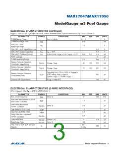
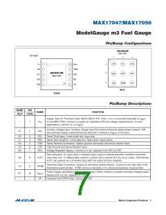
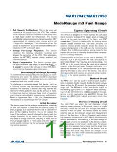
Pin/Bump Configurations
MAX17050
TOP VIEW
1
2
3
+
+
AIN
SCL
CSN
V
1
2
3
4
5
10
9
V
BATT
TT
A
B
AIN
SCL
SDA
CSN
THRM
ALRT
REG
V
ALRT
REG
CSP
BATT
8
MAX17047
7
C
SDA
THRM
EP
CSP
6
WLP
TDFN
Pin/Bump Descriptions
BUMP
WLP
PIN
NAME
FUNCTION
Supply Input for Thermistor Bias Switch (MAX17047 Only.) V is connected internally to V
TDFN
TT
BATT
—
1
V
on the MAX17050. Connect to supply for ratiometric AIN pin-voltage measurements. In most
TT
applications, connect V to V
.
BATT
TT
Auxiliary Voltage Input. Auxiliary voltage input from external thermal-measurement network. AIN
A1
2
AIN
also provides battery insertion/removal detection. Connect to V
, if not used.
BATT
A2
C1
A3
C3
B3
3
4
5
6
7
SCL
SDA
CSN
CSP
REG
Serial Clock Input. 2-wire clock line. Input only.
Serial Data Input/Out. 2-wire data line. Open-drain output driver.
Sense Resistor Connection. System ground connection and sense resistor input.
Chip Ground and Sense Resistor Input
Voltage Regulator Bypass. Connect a 0.1FF capacitor from REG to CSP.
Alert Indication. An open-drain n-channel output used to indicate specified condition thresholds
have been met. A 200kI pullup resistor to power rail is required for use as an output. Alternatively,
ALRT can operate as a shutdown input with the output function disabled.
B2
C2
8
9
ALRT
Thermistor Bias Connection. Supply for thermistor resistor-divider. Connect to the high side of the
THRM
thermistor/resistor-divider. THRM connects internally to V during temperature measurement.
TT
Power-Supply and Battery Voltage-Sense Input. Kelvin connect to positive terminal of battery pack.
Bypass with a 0.1FF capacitor to CSP.
B1
—
10
—
V
BATT
EP
Exposed Pad (TDFN Only). Connect to CSP.
����������������������������������������������������������������� Maxim Integrated Products
7

 MAXIM [ MAXIM INTEGRATED PRODUCTS ]