MAX17047/MAX17050
ModelGauge m3 Fuel Gauge
POSITIVE
POSITIVE
POWER BUS
POWER BUS
PACK+
PACK+
+
V
BATT
SDA
THRM
CSP
V
AIN
SCL
CSN
BATT
V
TT
AIN
SCL
SDA
CSN
THRM
ALRT
ALRT
REG
C
VBATT
C
VBATT
MAX17047
C
REG
REG
CSP
REG
MAX17050
EP
C
REG
NEGATIVE
POWER BUS
NEGATIVE
POWER BUS
PACK-
PACK-
R
SNS
R
SNS
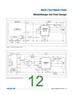
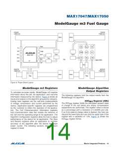
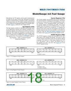
Figure 8. Proper Board Layout
ModelGauge m3 Registers
ModelGauge Algorithm
Output Registers
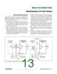
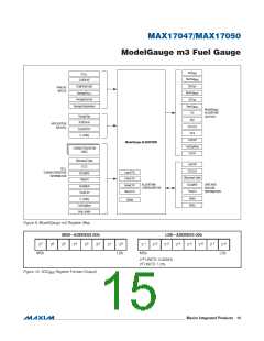
To calculate accurate results, ModelGauge m3 requires
information about the cell, the application, and real-time
information measured by the device. Figure 9 shows all
inputs and outputs to the algorithm grouped by category.
Analog input registers are the real-time measurements
of voltage, temperature, and current performed by the
device. Application-specific registers are programmed
by the customer to reflect the operation of the applica-
tion. The Cell Characterization Information registers
hold characterization data that models the behavior of
the cell over the operating range of the application. The
Algorithm Configuration registers allow the host to adjust
performance of the device for its application. The Save
and Restore registers allow an application to maintain
accuracy of the algorithm after the device has been
power cycled. The following sections describe each
register in detail.
The following registers hold the output results from the
ModelGauge m3 algorithm.
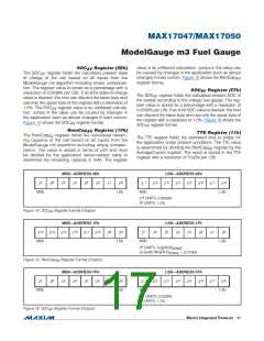
SOC
Register (0Dh)
MIX
The SOC
register holds the calculated present state
MIX
of charge of the cell before any empty compensation
adjustments are performed. The register value is stored
as a percentage with a resolution of 0.0039% per LSb.
If an 8-bit state-of-charge value is desired, the host can
discard the lower byte and use only the upper byte of the
register with a resolution of 1.0%. Figure 10 shows the
SOC
register format.
MIX
���������������������������������������������������������������� Maxim Integrated Products 14

 MAXIM [ MAXIM INTEGRATED PRODUCTS ]