MAX17047/MAX17050
ModelGauge m3 Fuel Gauge
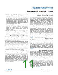
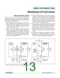
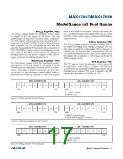
3) CSN and CSP traces should make Kelvin connections
Recommended Layout
to R
. The device measures current differentially
SNS
through the CSN and CSP pins. Any shared high-
current paths on these traces will affect current-
measurement gain accuracy. PCB resistance that
cannot be removed can be compensated for during
characterization of the application cell.
Proper circuit layout (see Figure 8) is essential for
measurement accuracy when using the MAX17047/
MAX17050 ModelGauge m3 ICs. The recommended
layout guidelines are as follows:
1) Mount R
as close as possible to PACK-. The
SNS
4) V
capacitor trace loop area should be minimized.
device shares both voltage and current measure-
ments on the CSP pin. Therefore, it is important to limit
the amount of trace resistance between the current-
sensing resistor and PACK-.
BATT
The device shares the V
surement and IC power. Limiting noise at the V
pin for both voltage mea-
BATT
BATT
pin is important to current-measurement accuracy.
5) REG capacitor trace loop area should be minimized.
The helps filter any noise from the internal regulated
supply.
2) V
trace should make a Kelvin connection to
BATT
PACK+. The device shares the V
pin for both
BATT
voltage measurement and IC power. Limiting the
voltage loss through this trace is important to voltage-
measurement accuracy. PCB resistance that cannot
be removed can be compensated for during charac-
terization of the application cell.
6) There are no limitations on any other IC connection.
Connections to THRM, ALRT, SDA, SCL, V , and
TT
AIN, as well as any external components mounted to
these pins, have no special layout requirements.
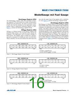
V
< V
BIAS
INTERNAL
2.8V < V
+ 0.6V
BIAS
CHARGER WITH
CHARGER WITH
INTERNAL
BIAS
V
+ THRM
TT
MAX17047
MAX17047
AVAILABLE
V
BIAS
V
V
TT
TT
V
V
SYSTEM
VOLTAGE BASED
ON EXISTING
CHARGER REQUIREMENTS
SYSTEM
V
V
V
BATT
P
P
INTERNAL
P
BATT
ON DURING
CHARGE
OFF DURING
DISCHARGE
THRM
AIN
THRM
AIN
CSP
CSP
THERMISTOR
INSIDE
CELL PACK
THERMISTOR
INSIDE
CELL PACK
MAX17047 + CHARGER
WITH EXTERNAL BIAS
MAX17047 + CHARGER
WITH INTERNAL BIAS
PK-
PK-
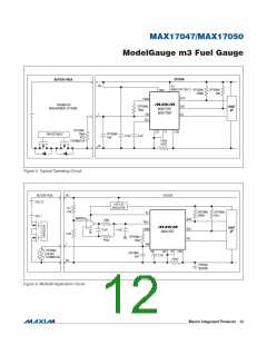
Figure 7. Operating Circuits that Share Pack Thermistor with System Charger
���������������������������������������������������������������� Maxim Integrated Products 13

 MAXIM [ MAXIM INTEGRATED PRODUCTS ]